/This guide moved from Kingpincooling.com forums I put together a mounting guide for the new KPC Inferno hot plate. The new heater plate kit was designed to keep the surrounding pcb socket area as well as DIMM slot area and cpu vrm from excess freezing. When using most forms of sub zero cooling, it can actually cause bad performance/signaling, cold related problems on the motherboard pcb itself, as well as water and ice everywhere which can lead to shorting and eventual hardware failure. Using the plate regularly can add hours and hours to bench sessions while greatly extending the life of motherboards when using extreme cooling.
These kits are designed as a bolt on upgrade for ALL KPC CPU containers, past, present, AND future 
KPC Inferno plate does everything automatically and efficiently as possible, all user needs to do is plug into 6 pin PCI-E connector on system PSU and that's it! From phase change cooling(-40c to -60c), to Dry Ice(-55c to -70c), to Cascade cooling(-80c to -120c), to full out LN2 cooling and beyond(-193c to ***), the inferno can calibrate and tune itself according to negative thermal loading on the PCB. End user only needs to disconnect power supply when not in use.
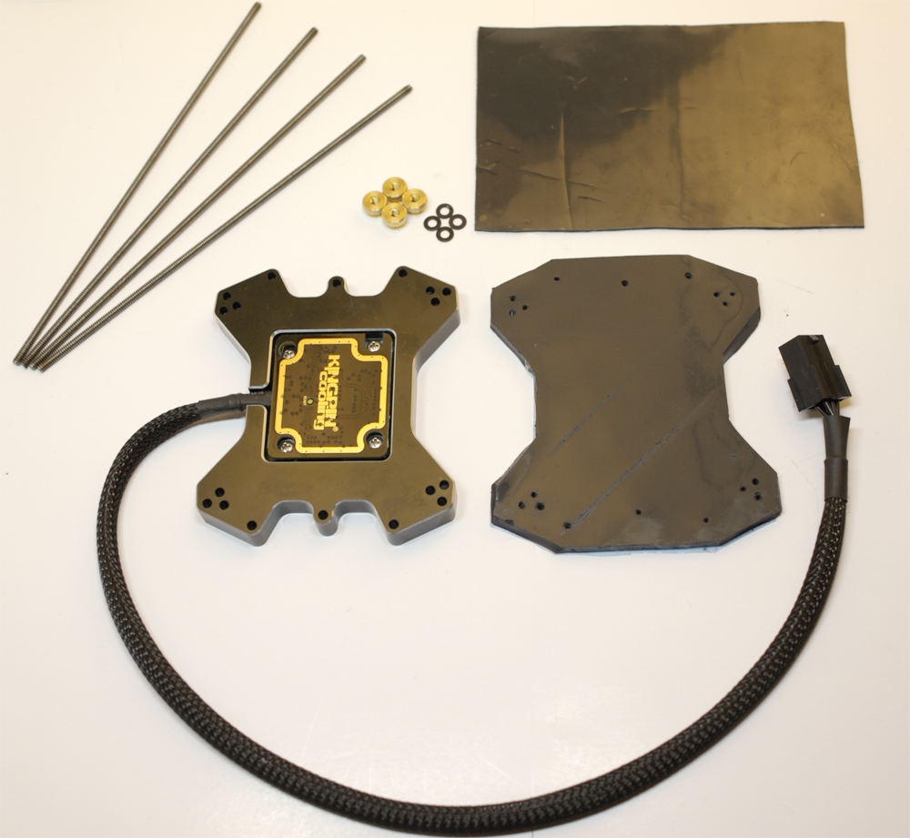
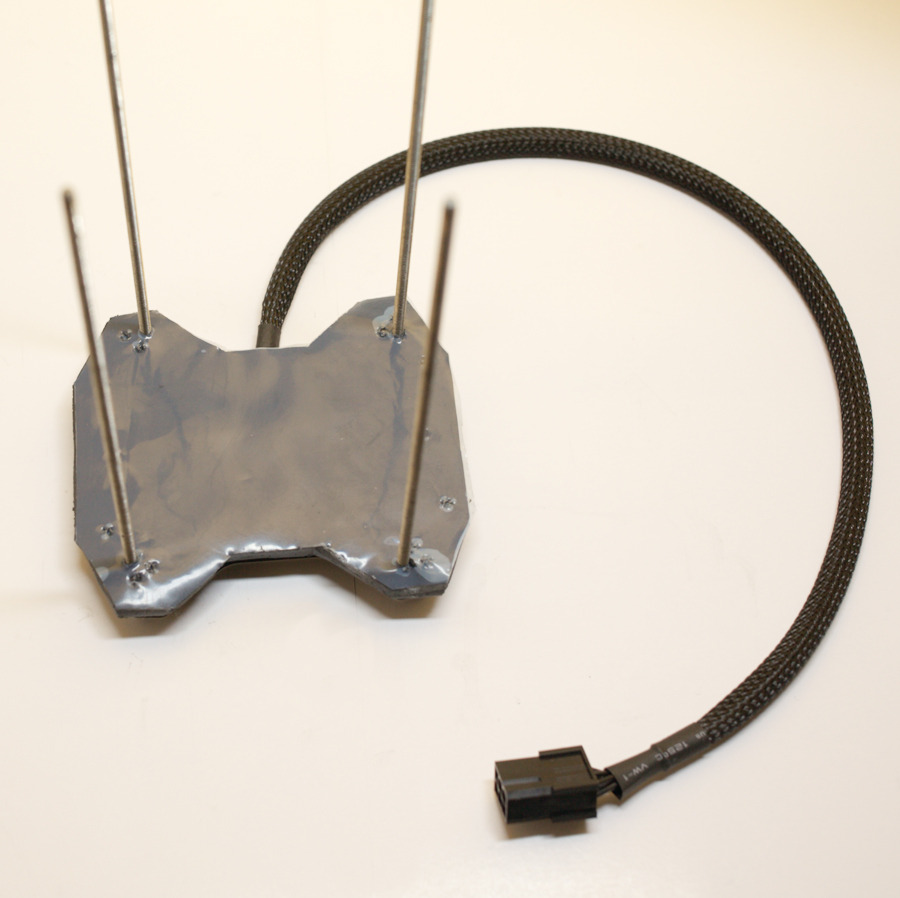
Inferno hot plate kit includes:
- Fully assembled heater plate and power cord (6 pin PCI-E)
- Large re-usable die cut thermal pad
- Small thermal pad for better thermal transfer around sockets
- 4 Thumb nuts for compression mounting
- 4 Washers
- 4 Rods compatible with ALL KPC cpu container kits

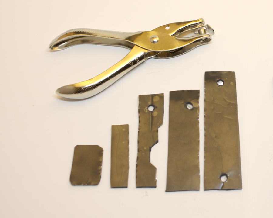
First step is to take the included thinner thermal pad and cut strips for around and inside the socket. This will make the thermal conductivity of the mounting optimal. Material from both thermal pads is completely re-usable, so take care when installing and removing to different boards and it will last long a time:
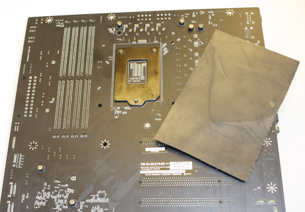
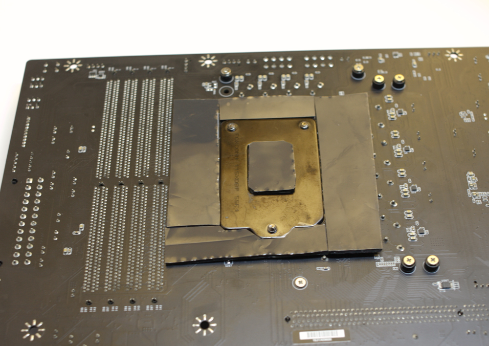
Once the pieces for around the socket have been cut, set them aside and prepare around the socket with LET, grease, or other protective PCB application. It is entirely up to user preference what is used. The heater plate can tremendously help with frost and water on pcb, however I still recommend to do put something on pcb inside the usual pot mounting area just around the socket as well as the same location on backside of the motherboard. Assuming PCB is prepped and ready, now add the location for the socket holes before you remove the plastic on BOTH sides of thermal pad material. I use one of these paper hole punchers for making holes on thermal material and foam tape etc, works nice.
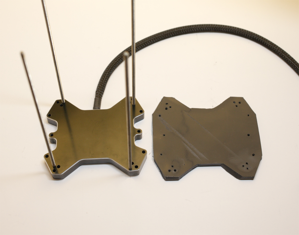
Take the heater plate and the larger thermal pad and make note of the orientation of the holes relative to both parts. The holes in the pad match exactly the holes in the plate. If you install the pad upside down, the holes wont match up and you risk damaging the thermal pad. Also remember to REMOVE the plastic from BOTH sides of the thermal bad before fully installing.
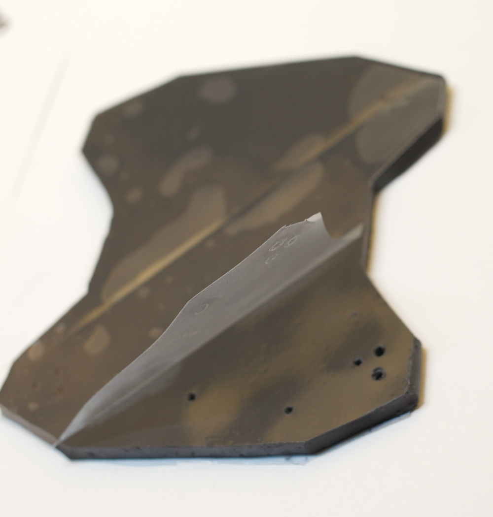
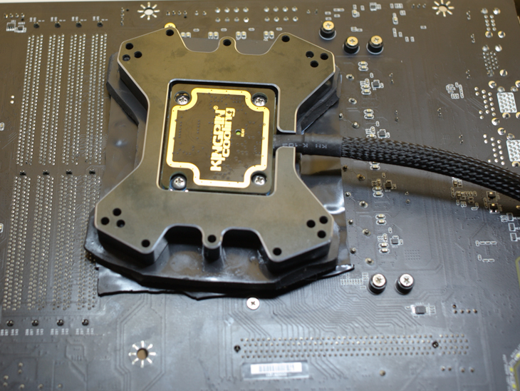
With clear plastic removed, place the thermal pad over the correct rod hole mounting locations of the platform being used, and slide the thermal pad down sticking it down to the heater plate as pictured (NOT CONTAINING PCB)
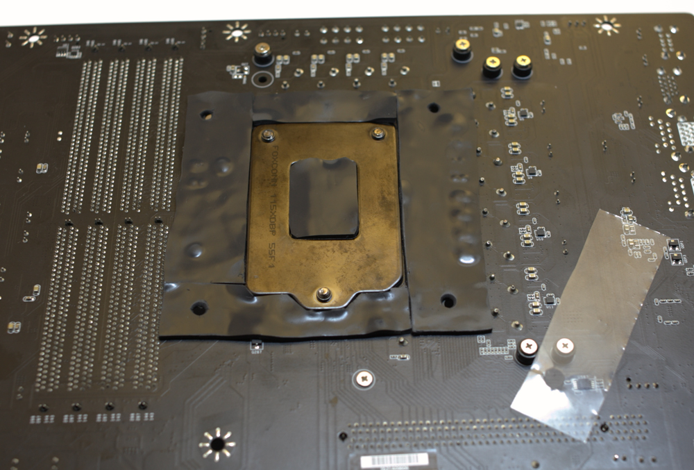
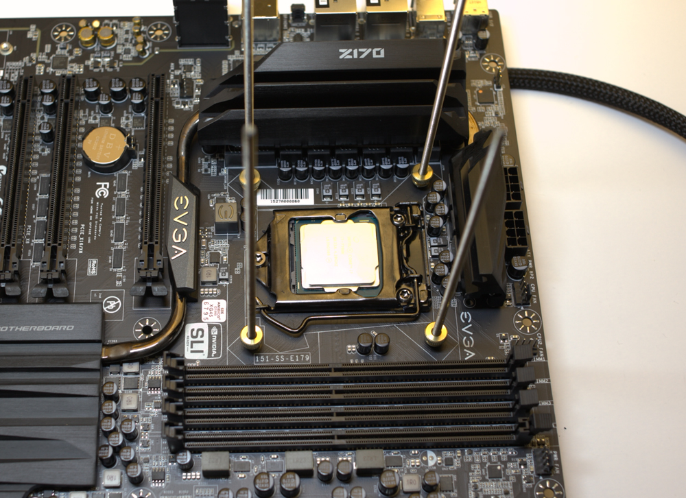
Now peel off the blue plastic on the mounting side of the plate and simply mount the heater plate similar to usual KPC cpu container mounting plate. Slide the rods through the motherboard pcb holes from backside of board until the plate is snug against the back of the board.
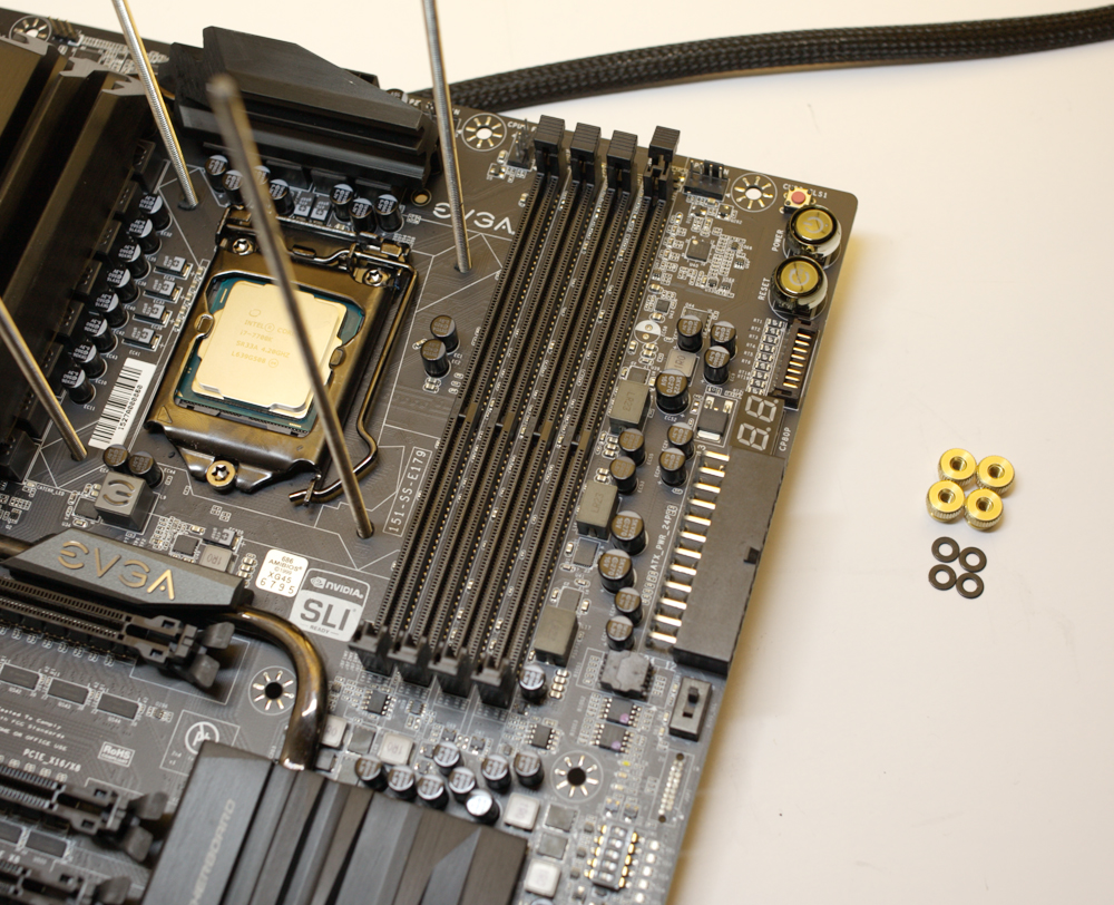
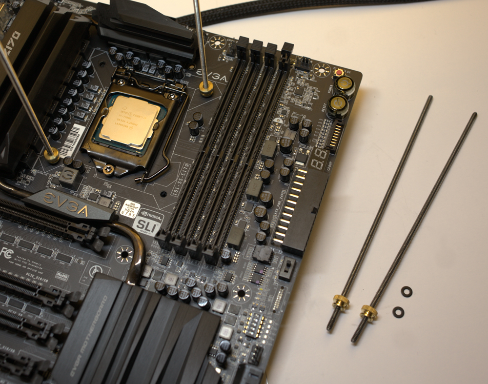
Now set the motherboard down onto a firm flat surface and time to install the top compression nuts + washers. Rather than having to turn the nuts all the way down the rods to the motherboard, there is a much easier way. Just remove two rods at a time diagonally and put the washers and thumb nuts at the bottom of the rods, then simply remount through the holes back to the plate. By doing only two diagonally at a time, this keeps the plate aligned with the mounting holes making it much easier to add the nuts.
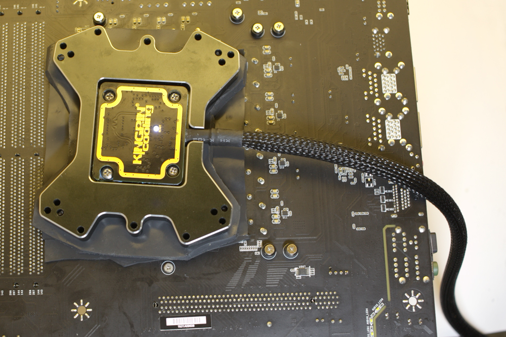
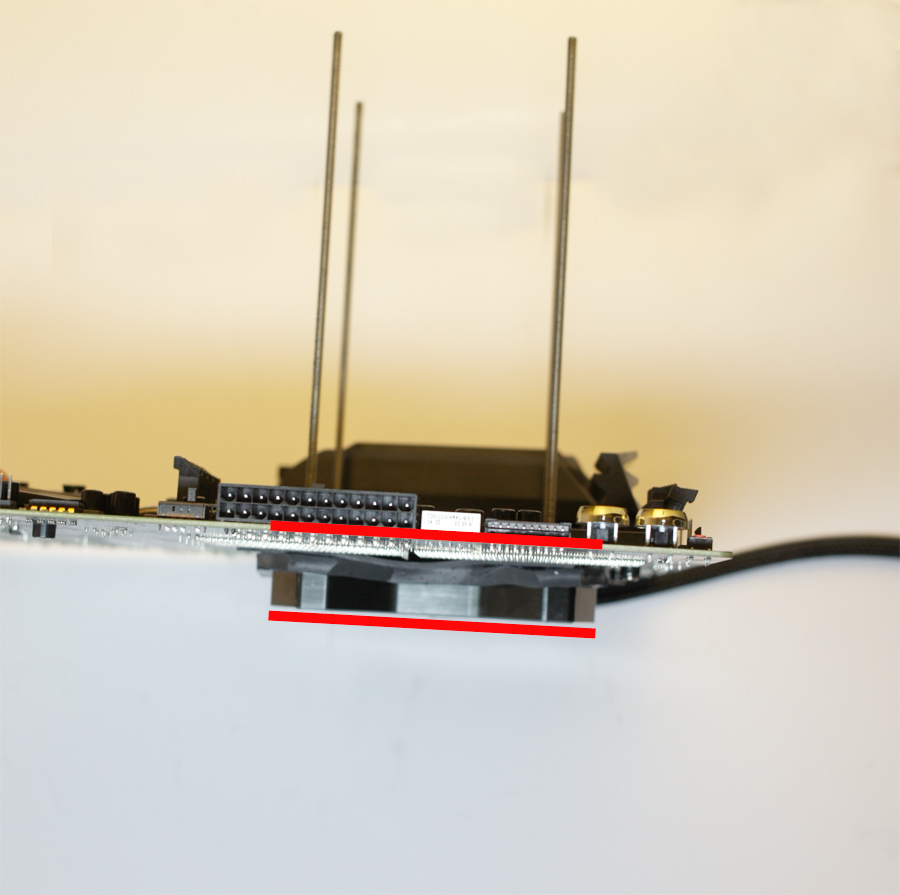
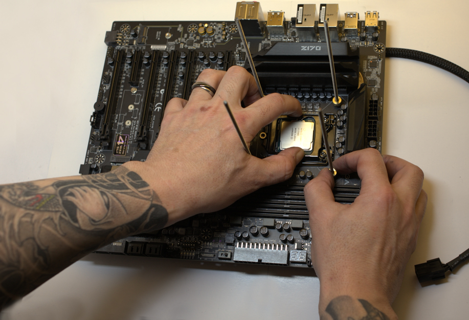
Once all 4 washers and nuts are added, its time to level off and compress the heater plate for final step in mounting. NOTE, it is very important that the heater plate is mounted as level and parallel with the pcb of the board as possible. If you don't do this and the plate is not mounted flat and level, it can risk shorting something on back of mobo as well as lowering the heaters performance. A really easy way to get a perfectly flat tight compression on the heater plate and board, is to push down right at the socket area on the flat hard surface so the plate is flat against the table surface, then turn down the nuts one by one by equal amounts while maintaining centered pressure on the socket area. Make it tight enough that it puts a nice squeeze on the thermal pad material, the tighter the compression, the more thermal transfer. Using top mounting nuts on your container mounting also give a nice plate mounting plane to mount heavy containers to, providing socket and cpu pcb support.
Mounting is now complete and its ready to rip! You can plug in the heater to test and make sure its working correctly before overclocking begins. Plug to 6 pin PCIE connector on system, and wait a minute or so for it to be active. When "ready" light comes on, the plate is working 100% optimal. When light goes off, the plate is actively recovering its temps and once operating temp is reached, light comes on again.
KPC Inferno heater plate is able to monitor and self adjust plate loading based on relative pcb temps

As you go colder, it works harder and it can handle any kind of cooling thrown at it. Always remember to plug it in before you bench is all you need to do