This is a brief documentary of my converting an old Power Mac G5 case to hold an EVGA SR-2 Classified motherboard. I installed Windows on it but you could return it to being a high-ish end (h)ackintosh if you insisted.
This is not a simple affair. There is much cutting, a little custom fabrication, and for me there was considerable head-scratching. The motherboard fits, but only just. This was built from scraps that came through my shop over about a year and a half. The odds you will be able to duplicate this exactly are pretty low, but this will give you an idea of what's necessary to use this board in this case.
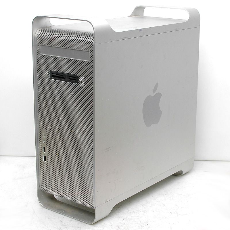
The Power Mac G5 case is a visually appealing case. Visual design was a strong point of Apple computers at this point in their history, and fortunately for us, the dual CPU G5 motherboard was HUGE. Unfortunately, it also only had 4 expansion slots and nothing like a standard PC footprint. All the internal components have to come out of the case, and this is not a reversible process. The rear of the case must be destroyed but you can repair it with new parts to look nice if you are clever.
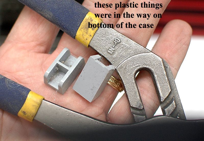
To begin with, remove the contents of the case, including everything. Instructions can be found elsewhere online so I'll spare you that. The divider between the compartment holding the drives and the compartment holding the motherboard (the PCI Divider) is a PITA. Remove little clips holding the latches for the side cover, remove the latches, pull the latch bar free, and tilt the divider out. You don't have to bend the PCI Divider to get it out of the way like I did before I figured out how to remove it. You do have to remove it though, because you are going to need to cut it if you want to copy this case mod. Pay attention to which special screws came from where.
First I started by just seeing if the board will physically fit. Others have done this conversion so I was pretty sure it would.
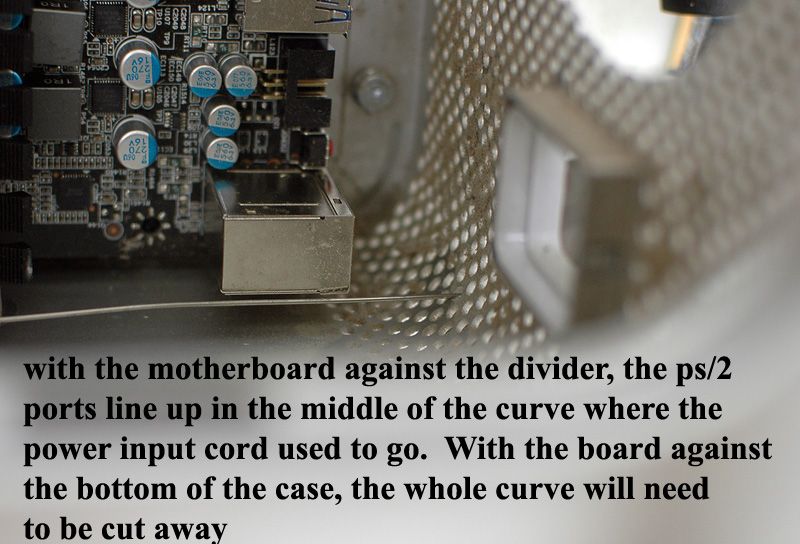
The line across the bottom is a wire, shoved through the back of the case at the level of the PS/2 connector to show me how far down I needed to cut the rear of the case. The motherboard doesn't fit. In order to get the I/O connectors and expansion cards to the rear of the case, you HAVE to cut the case.
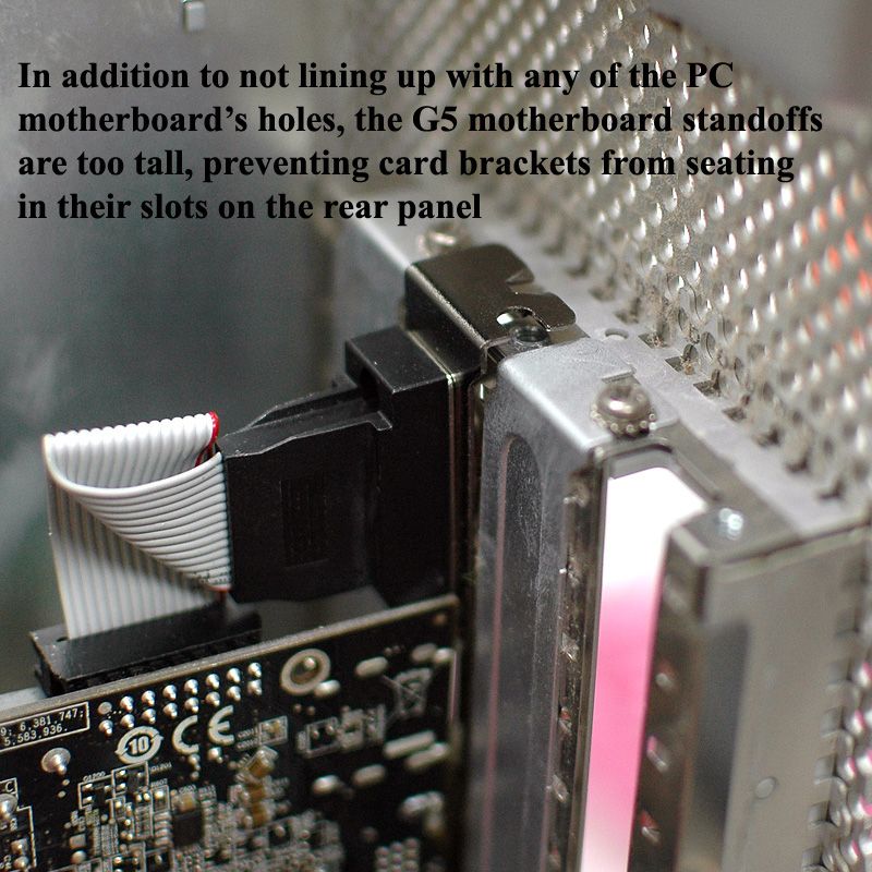
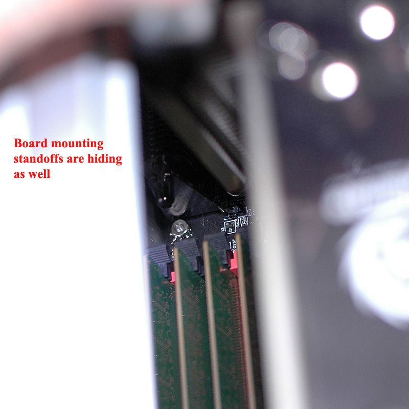
Just setting the board in the case with a little video card mounted for reference, I could see the standoffs were too tall for this board.
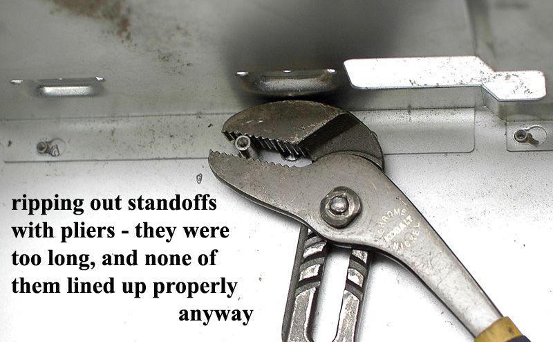
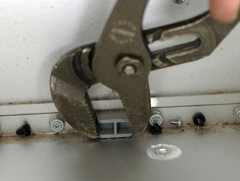
You have to pull all the standoffs and other stuff cluttering up the non-opening side of the case. This is going to be our motherboard tray, so it's got to be free of all protrusions.
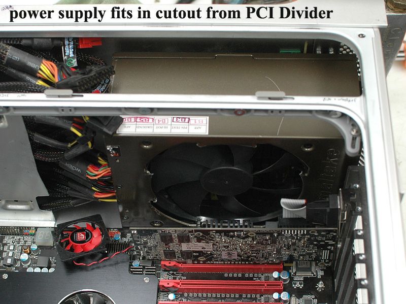
This board wants a big power supply. This is a big power supply. I think even with a regular ATX size power supply, you'd still have to cut the PCI Divider unless your ventilation fans are on the ends of the power supply, and you don't mind using ONLY the ventilation holes around the optical drive to cool your power supply. This fan is pretty obviously not on the end of the power supply. Plus I don't even want to THINK about how much of a hassle it would be to route the cables from the power supply through the little tiny holes provided for the G5's cables to the hard and optical drives that used to live here. So, I cut the divider. I did NOT want to cut the top of the ventilated rear panel, so instead of flush-mounting the power supply, I used standoffs. The standoffs are different lengths to accomodate the curvature of the case.
The red fan is for the card installed on the motherboard. This is a bit of a throwaway video card, so disregard the fan eh!
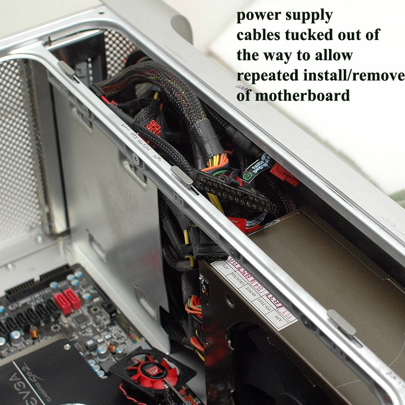
I had already put the motherboard in and out a bunch of times and the wires from the power supply were just in the way. I tucked them into the optical drive bay for now.
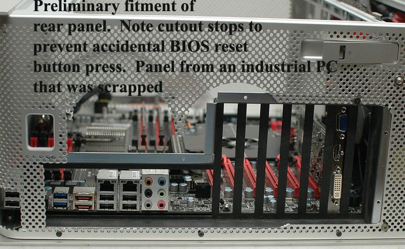
I had the "luxury" of using the rear panel from an industrial rack-mounted computer that had been scrapped. It has the right number of expansion slots, and barely-barely fits. No, I don't know what brand of computer case this panel came from. I have seen other people who had this panel laser-cut from raw metal sheets. I suppose it's possible to get by with lesser brackets just to keep the video cards from flopping around, but hey, this is what I had and hey, it worked. Fitting the rear panel was a bit of a hassle. There is only-just enough room for the motherboard, and there's really not room enough to miss by even 1/4" when installing the rear panel. I test fitted this a BUNCH of times to be sure I would get the parts in the right place. Do not try to rush this, or you will possibly screw up the whole job.
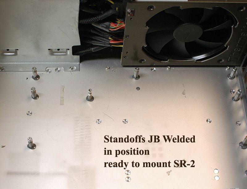
Eventually I came to understand I would have to make custom standoffs. I want to say they were like 16.5mm long, which was surprisingly long to me. I cut them off and filed the ends to length, and then installed the standoffs on the motherboard. JB Weld was my epoxy of choice. It is probably a good idea to clean the case with alcohol or acetone so the JB Weld will hold. Glom some epoxy on the end of each standoff, and put the motherboard in the exactly-right position. Depending on the chemicals you use, you will have <5 minutes to a few hours to get it in the right position (read the directions on your chemicals!). I left the board in the case, with the case lying flat on its side for about a day to let the epoxy cure. Remove the board and you have... standoffs exactly where they need to be, TADA!!!
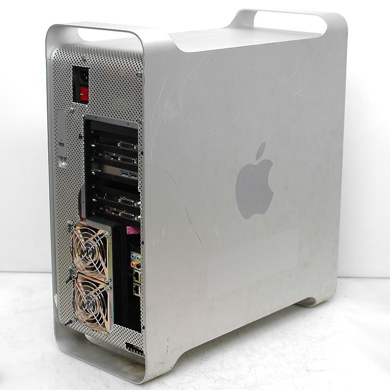
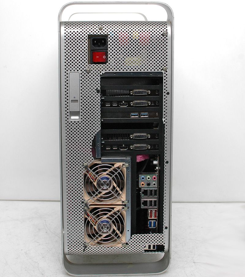
I had to drill a few new holes and find screws and nuts to fit, but eventually I was able to mount the rear panel solidly to the case along one side. The other side, not so solidly. You can see the cutout I had to make to clear the PS/2 and USB connectors. The BIOS reset switch lives behind the remaining section of rear panel. It's blocked but accessible by poking a wire through one of the holes.
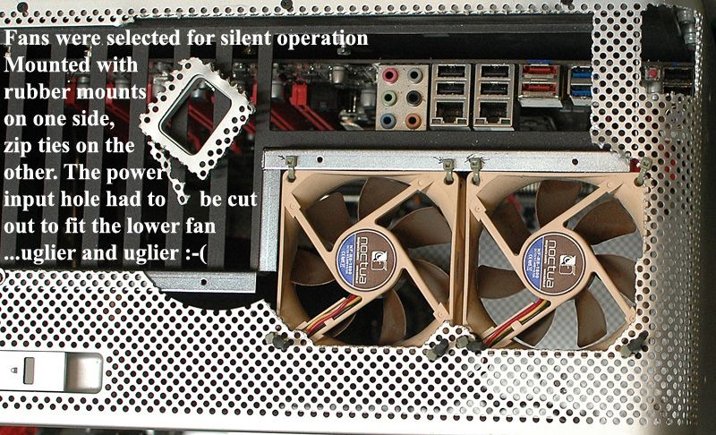
The rear panel exhaust fans are 80mm and that's about as big as would fit. I used plastic zip ties to hold them in place. Fortunately, this is the side of the case I never will have to see once the computer is installed.
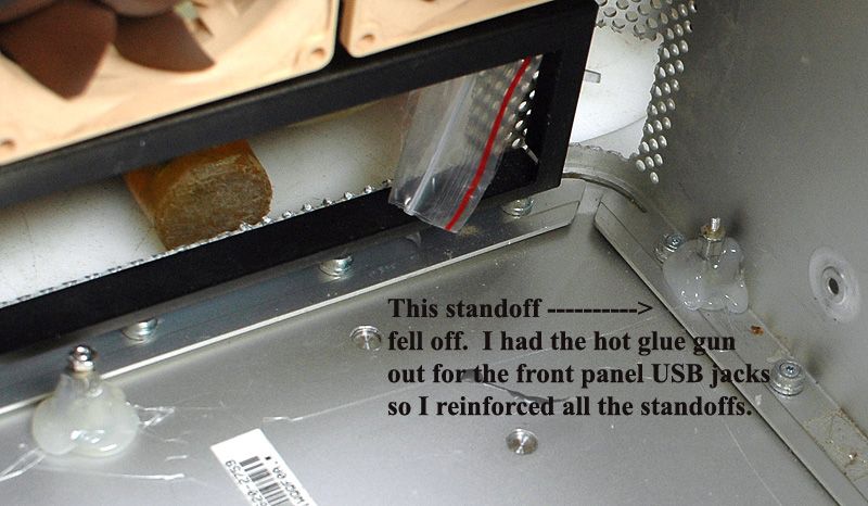
One of the standoffs fell off. Boo! I hot-glued a big pile of glue around all the standoffs. That'll hold them.
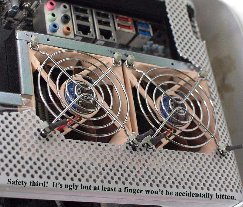
I found some wire grilles, so the fans are no longer going to bite anyone. The long black things are rubber vibration-isolating mounts from a different fan from yet a third computer case. Dell uses these alot, but I don't know if these specifically came from a Dell.
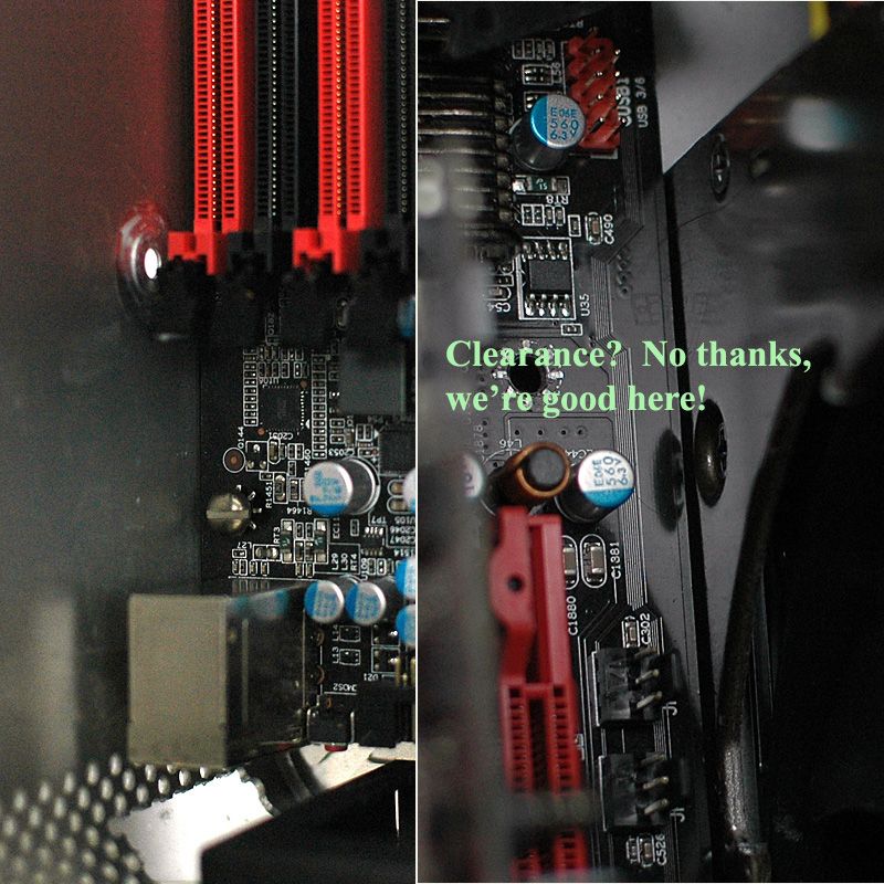
Okay so the glue is cured and the standoffs are ready to accept the SR-2. In we go! How much clearance is there? Yes, there is clearance. No, there is not more than a few millimeters of clearance. It fits, anyway.
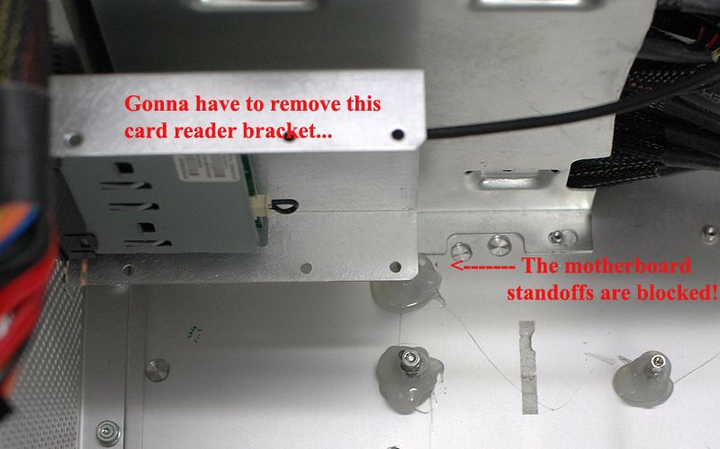
I had installed the bracket for the memory card reader already. I had to pull it out to install the motherboard.
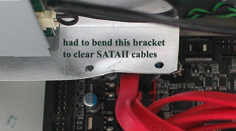
Then I had to modify the bracket to fit SATA II cables.
Remove the front panel power switch and I/O circuit board now. Do any sheet metal work on the front panel now. I'll show you why later.
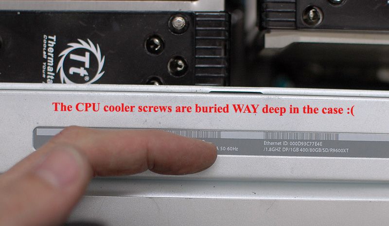
My CPU coolers are biggish air coolers. They had to come out to allow the board to fit in the case when the standoffs were installed. One of the coolers wasn't so bad to reinstall. The other one, the screws are literally inaccessible. You could drill holes in the case to let a (long) screwdriver in there, but I used small tools and may have said some bad words when tightening down the CPU coolers.
Oh yes, the board mounting standoffs are also impossible to reach. This is about the suckiest part of this whole install.
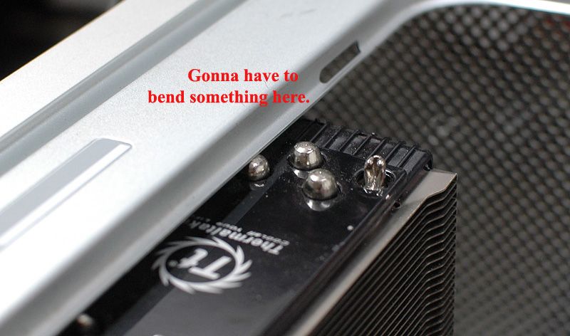
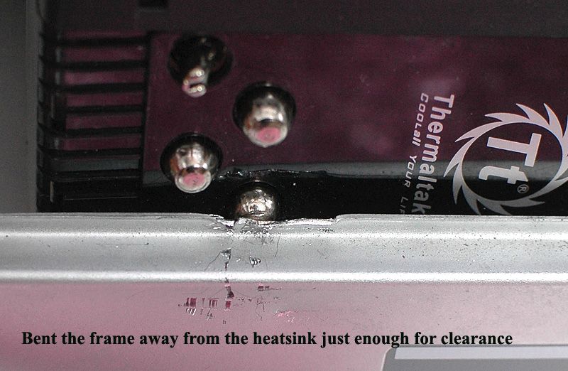
Did I mention my coolers were big? Big as in, they are too big to physically fit in the case - but only just!
OK so I had put the power and front panel connectors off till last, which was a mistake. I had to remove a CPU fan just to get the board out.
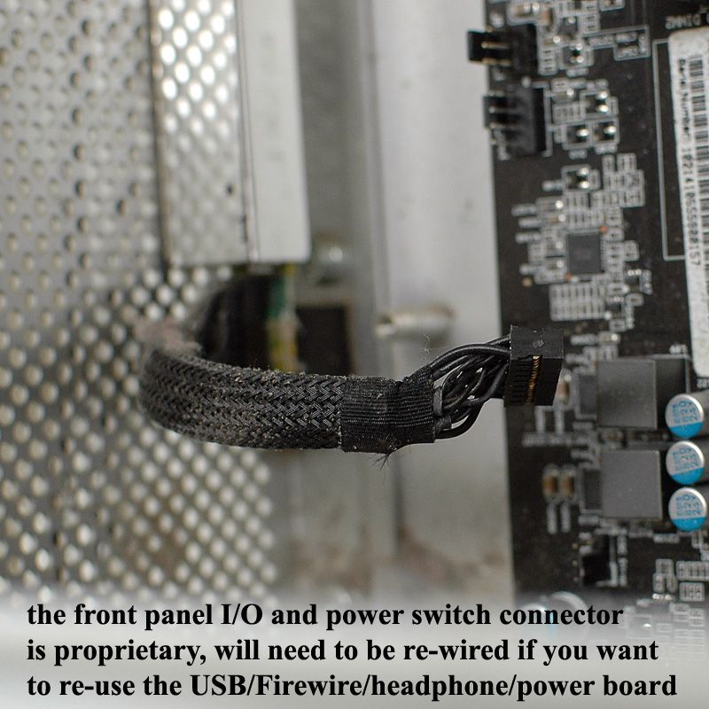
The SR-2 doesn't have Firewire capability. I use both front panel USB ports on my current rig. This adds up to . . . not having to deal with the front panel circuit board at all! Some people have struggled with rewiring the front panel I/O wire to work with their motherboards. I've avoided that altogether.
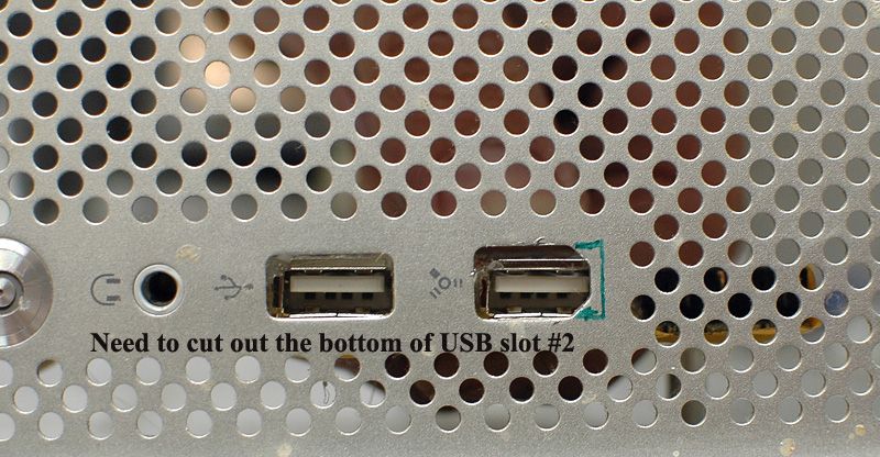
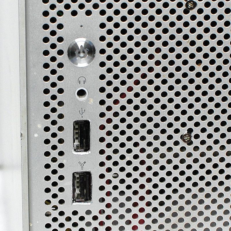
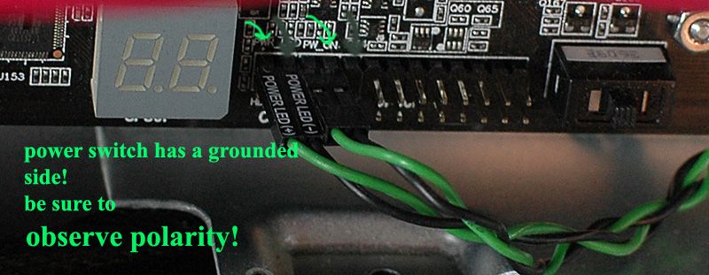
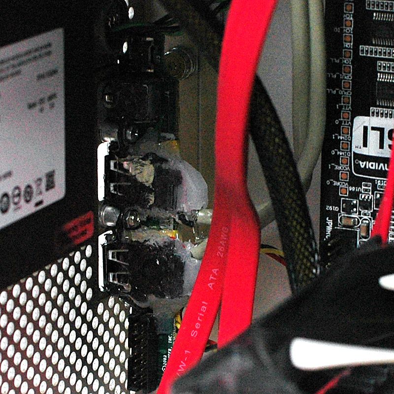
I grabbed the rear panel USB bracket and cables from yet another decommissioned computer, split the USB connectors enough to fit properly behind the holes on the G5's front panel, and hot-glued the USB ports in place. This is tricky, and it would be VERY easy to get these misaligned. Careful not to glue over the screw brackets. In theory I could use the audio jack . . . in practice I'll be ignoring this jack and using the rear panel audio from the motherboard. The little connector on the far-right is for the power switch and its LED The black connector on the left is signal I/O. You can ignore both these if you are doing what I did. I smashed/cut the USB and firewire connectors from the Apple front panel I/O board and glued these USB ports in their places. Carefully!
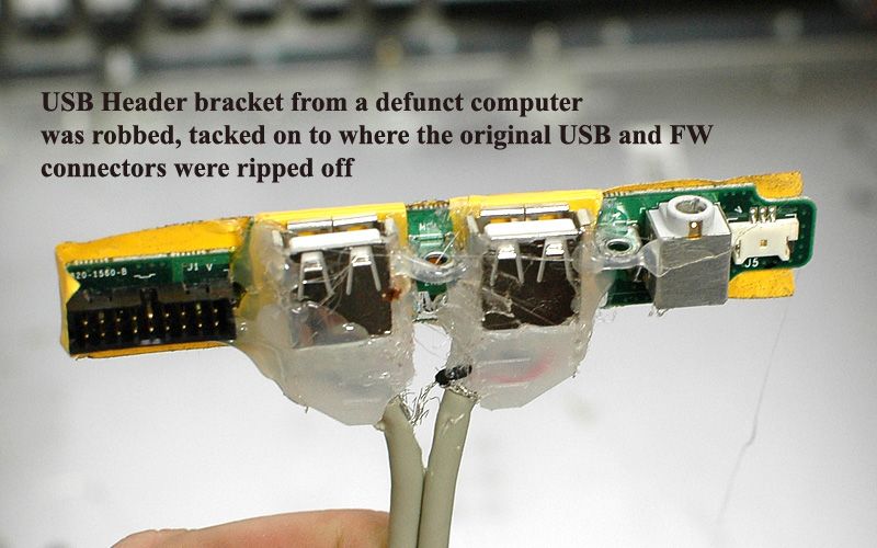
Of course the shapes and sizes are different. I trimmed the firewire port hole a little to fit a USB cable.
This is my final form!
The power switch and its LED are a little tricky. IF you have read this page and know what you are doing, you won't have to remove the little circuit board from its home. You can just solder wires onto the contacts with the board in place. I didn't have this to inform me so I pulled the switch board. The switch is a pretty simple affair. A small metal dome is taped in place, and pressing it makes the contact for the power switch. There is a single LED. These share a common ground wire, and current "regulation" for the LED is accomplished by a resistor in the GROUND side of the LED. Then both the switch and the LED share the ground wire, and so the same solder pad. The + side of the power switch and LED have their own contacts. I used the Power LED and Power Switch wires from yet another decommissioned computer, and soldered them in place on the G5's power switch PCB.
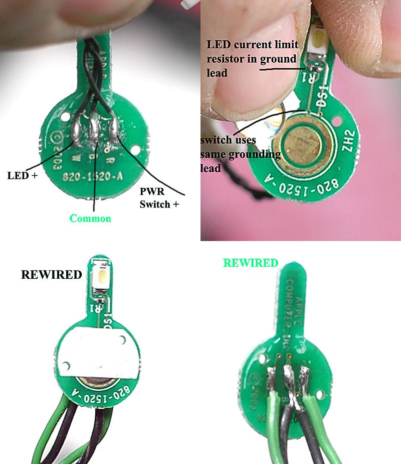
Observe polarity on the power switch.
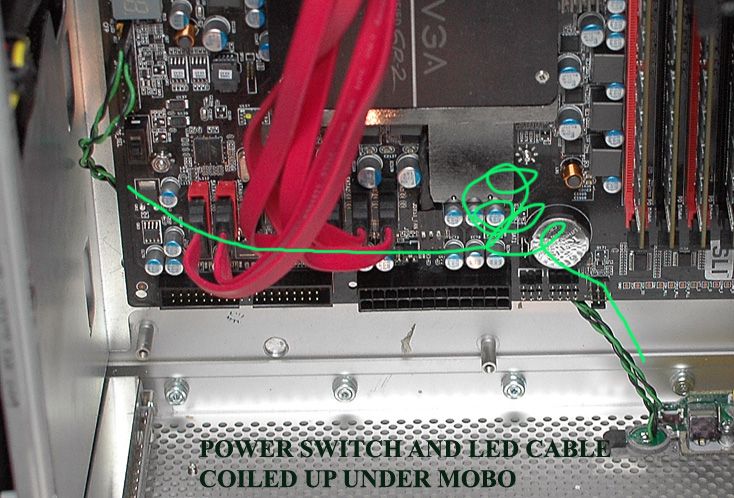
My wires were longer than necessary, so I just coiled them out of the way under the motherboard.
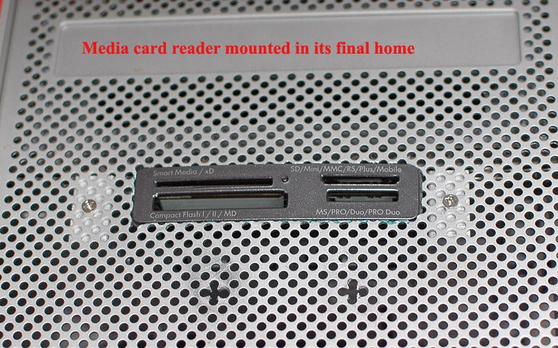
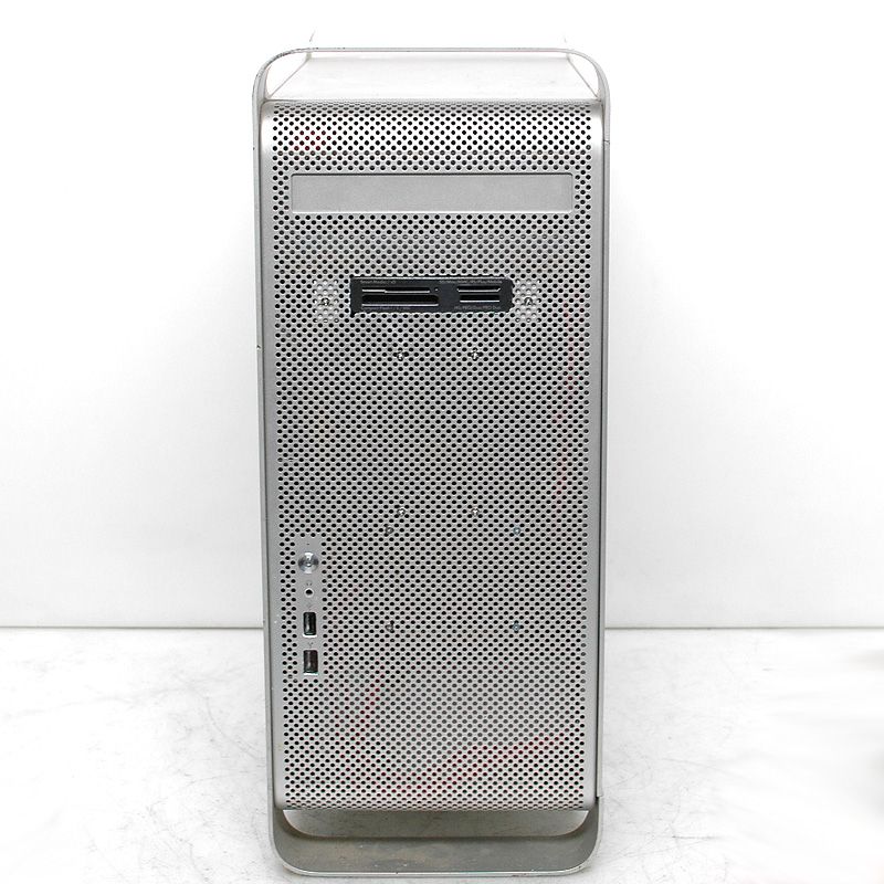
The memory card reader you use will dictate the cutout you make in the front panel. Here's mine, final-fitted. If it bothers me enough that the bracket can be seen through the front of the computer, I may go back in and color the bracket for the card reader solid black.
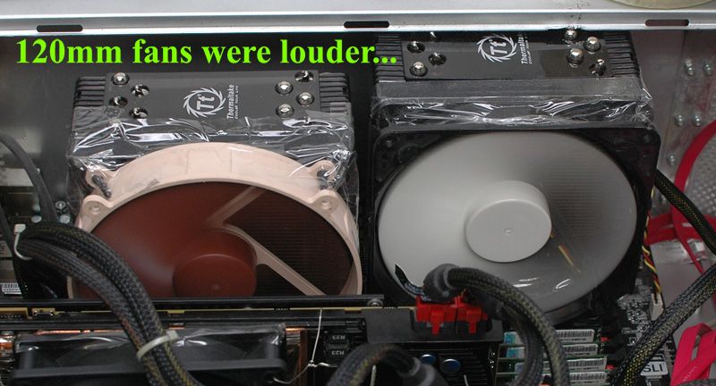
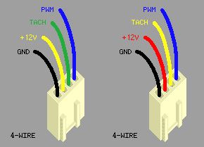
My CPU cooling fans were 120mm 4-pin PWM types. For whatever reason, my motherboard wasn't regulating the fan speed on the PWM fan header. This made one of the fans always run at full speed, and it was audible. This is a problem for me. I value quietness of fans above aesthetics, by a lot - It's not even close. So I grabbed two 140mm fans, one being my favorite type of Noctua that I wish I'd kept the other one of the two of these I had once upon a time. Oh well. Mismatch it is, then, and taped in place. But the motherboard can control the 3-pin fan speed, so there we go.
Finally everything was installed enough to boot the computer. This is a workstation and I value our data, so I used ECC memory. Lots of it. Then the first program I ran was Memtest.
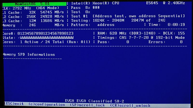
Later, after Windows was installed and a bit of conservative overclocking done (SUPER easy 3GHz on 2.4GHz chips, thanks to Shamino!), I ran Prime95 to test stability. For a day. Then I changed the settings and ran it for another day and a half. No errors, and that's good. It was also good as a low-powered space heater! The fans were running at full speed and they were unobtrusively quiet. That's a build, folks.
All that's left is the "after" pictures.
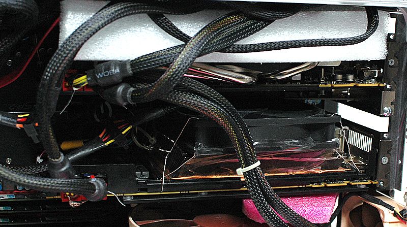
This bears some explanation. The white and pink extra bits are foam panels, installed to help channel cool air to the 2nd GPU and power supply, and to route hot air from the CPUs out the back of the case instead of having it swirl around inside.
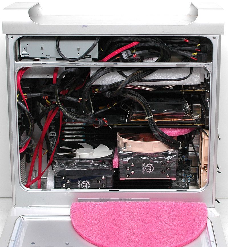
Fresh air is drawn in the front panel. The power supply and upper GPU are sucking pretty hard toward the top of the case, and the power supply vents out the top/rear of the case. Hot air coming through both GPU coolers swirls around in the case, and it would take more baffling than I think is worthwhile in order to channel hot air straight out the back.The CPU coolers have a baffle near the front, a baffle over the top of the coolers, a baffle between the coolers, and a baffle between the upper cooler and the lower GPU. They draw air from inside the middle of the case, and vent out the back of the case. Two smaller exhaust fans aid the CPU fans, as well as taking some of the heat from the GPUs - unfortunately, through the CPU coolers but that's ok. The original optical drive's mounting screws and quick-release mount were reused, but I had to take the front panel off the drive to make it work right with the spiffing retractable optical drive door in the G5 case. The eject button is hidden and not useable. I don't love having only one optical drive, but I only rarely use both at the same time on my current rig and then only for the sake of convenience. Extra power supply wires are tucked up around the power supply, forming a mild airflow restriction to keep hot air from the PSU from blowing around in the case.
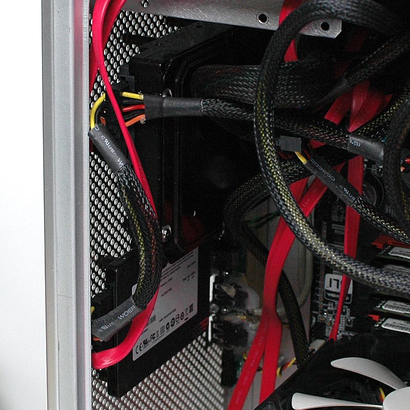
There are a few spare inches inside the front of the case, which is the only spare room available in the whole thing. I used standoffs to mount the hard drives off the front panel. This changes the hard drives from an airflow obstruction you can see, to a noise baffle in the shadows. Scroll up and look at the Front view of the finished computer again. You see screw heads, but you don't see the hard drives. I took a big magic marker and colored the hard drives all-black. I could have screwed these straight to the front panel, but you would be able to see them big-time, and they would block about 1/4 of the entire front panel, which is the cold air intake for the computer. I think this is a very big win as far as hard drive mounting goes. I could have used the stock Apple part, but a) that would be the ONLY stock part re-used inside the case and b) I cut it to remove the Apple hard drive bracket before I figured out how to get the PCI Divider out. The big drive is a 3TB data store, where I will keep ISO images and backup files. The smaller drive is a little solid state affair for a fast boot drive, and the SSD will be backing itself up by writing images of itself to the HDD.
I also black-markered all on the front panel USB connectors, to eliminate a source of BRIGHT reflective metal.
The GPUs are Radeon HD6970s. Both of these have rear (under the PCB) metal plates that aid heat dissipation a little. One has an aftermarket (ASUS) cooler, and it runs about 7º hotter at idle than the other, but that's only 40º so that's good enough for me. The other cooler is the stock AMD cooler. I removed the shroud and the blower, then used a long skinny metal thingy to separate the fins of the cooler, and some needle-nosed pliers to flatten and separate the fins. The 120mm fan is attached with safety wire and packing tape makes a good shroud. I found that I could not fit two GPUs with their coolers like this (they take about 3.5 PCIe spaces each!) and still have the power supply mounted like it is. I compromised and used the ASUS cooler on the upper GPU. Yes it looks cheezy. Aside from this thread, no-one will ever see this again so I don't care.
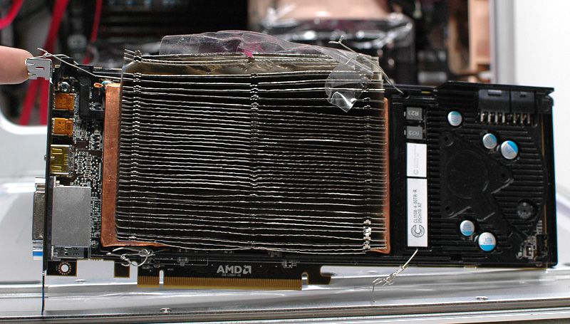
The stock cooler, modified with a 120mm fan like this, idles around 33º and never reaches 90º under load. The ASUS cooler also only gets up to 90º under load. I am pretty sure I could modify the fan control profiles and have them running cooler under load, but this isn't a mining machine so this is plenty of cooling for me. I only run two cards really because I use four monitors (!) at work. The 120mm fan was intended to be a CPU or case fan with a connector to fit a motherboard fan header, so I had to mix and match the wires, but it runs just fine off the GPU fan header.
I wish the power switch itself lit up, and there were a separate HDD power light, but oh well. I would like an eject button on the optical drive. I would have liked to have a cleaner-looking rear panel. I would like some more-professional-looking baffling for airflow control. I would like another hard drive for backup and another optical drive for the capacity. Talk about first-world problems.
Overall I am very pleased with how this came out.
********
Specs? You want specs? How about prices?
Price first: $0 plus lots of breaks and lunch hours. This entire build was made from SCRAPS. Yes, it is kindof a crazy place, where I work.
Motherboard: EVGA SR-2 $589
CPUs: Intel E5645 Engineering Samples. Retail for this chip was $611 each.
Power supply: Thermaltake Toughpower 1200AP $399
GPUs: AMD ATI Radeon HD 6970 $349 each
CPU coolers: Thermaltake Frio $55 each
Case: $50 on eBay or $3299 list for the whole G5
HDD: Seagate ST33000650NS $339
SSD: Crucial M4 128GB $271
Plus probably another $100 in fans, cables, etc.
So call it about a $7,000 list price build. For the cost of some "free" time. That'll do.
post edited by votefordavid - 2015/01/15 12:11:30