Official project repository on GitHub: https://github.com/1a2m3/SPD-Reader-Writer Latest binaries: https://github.com/1a2m3/SPD-Reader-Writer/releases Latest firmware:https://github.com/1a2m3/SPD-Reader-Writer/tree/master/firmware
Guide:
Part 1 - hardware
Wire up your Arduino + DIMM according to the schematic below:
 Click image to see full version. PDF can be found here
 The schematic shows modules divided into sections:
- Arduino section shows pins used on Nano V3 model. Use its 3.3V pin as a VCC source. If your Arduino doesn't have a dedicated 3.3V output, use a step-down 3.3V regulator, like LM7833. Pins labeled SA1_EN, HV_EN, and HV_FB can be assigned in "SpdReaderWriterSettings.h" file. 5V pin is required to power a 9V step-up converter (HV_SOURCE) and DDR5.
- HV_CTL and one of 9V sources are needed to enable and detect 9V on SA0 for RSWP related operations. Use either a step-up/boost converter (HV_SOURCE), or a 9V battery (HV_SOURCE_ALT), not both!
- SA1_CTL is used to switch pin SA1 on EEPROM between VCC and ground. This is needed because RSWP-supported EEPROMs used on DDR3 and DDR2 require different SA1 configurations to enable or disable RSWP. It is also used to prevent addressing conflicts when DDR5 is used.
Refer to your Arduino model pinout, on my Nano model SDA and SCL are A4 and A5, respectively:
https://www.arduino.cc/en/reference/wire
Parts list:
- Arduino: Nano V3 or any AVR-based model with I2C / TWI interface.
- OK1: PC817 or any general purpose optocoupler with a maximum collector to emitter voltage above 10V and a diode current below 40mA and forward voltage below 5V.
- R1, R2: Pull up resistor for I2C lines.
- R3: Current limiting resistor for optocoupler diode, values between 390Ω and 560Ω work fine.
- R4, R5: Voltage divider for HV feedback (HV_FB) on SA0. The values used will work for 5V and 3.3V Arduinos.
- R6: Pull up resistor for SA1 pin.
- D1: Any general purpose schottky diode.
- C1: 6.3V, 560uF
EEPROM pins to DIMM pins guide: DDR5: VIN_BULK=1, HSCL=4, HSDA=5, HSA=148, PWR_EN=151, GND=6*
DDR4: SA0=139, SA1=140, SA2=238, GND=2*, SDA=285, SCL=141, VDDSPD=284, WP/EVENT_n=78
DDR3: SA0=117, SA1=237, SA2=119, GND=2*, SDA=238, SCL=118, VDDSPD=236
DDR2: SA0=239, SA1=240, SA2=101, GND=4*, SDA=119, SCL=120, VDDSPD=238
DDR: SA0=181, SA1=182, SA2=183, GND=3*, SDA=91, SCL=92, VDDSPD=184
SDRAM: SA0=165, SA1=166, SA2=167, GND=1*, SDA=82, SCL=83, VDDSPD=168
* There are multiple GND pins on DIMMs, the table shows just one of them for each RAM type.
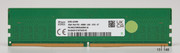
DDR5 UDIMM pins locations:
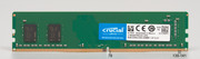
DDR4 DIMM pins locations:

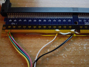
Obviously don't solder wires directly to DIMM contacts or motherboard solder points, get a spare slot from components resellers, like Digikey, or get a DIMM adapter, like the one pictured below. Those are cheap, and have pins labeled for easy identification.

Part 2 - Firmware
Upload
firmware to your Arduino once everything is assembled. Both files are required. Make sure the values in
SpdReaderWriterSettings.h match the pins names you used if your pins differ from the ones in the guide.
Part 3 - Windows GUI application
Latest application can always be found here:
https://github.com/1a2m3/SPD-Reader-Writer/releases The application requires
.NET framework 4 or later to be installed. Supported OSs are Windows XP SP3 and up. The application is compiled for x86 architecture, so both 32 bit and 64 bit OSs are supported.
Once your device is assembled and tested, start the program. Click "Connect" toolbar button, make sure selected baud rate matches the one you programmed, select your device from the list, and click "Connect" to start working:

Click on the device identified by its serial port name and EEPROM address detected on its I2C bus to start working with it.
Part 4 - Windows Console application
The program can read and write bytes, and enable or disable write protection. The operation depends on its command line arguments. The supported arguments are:
/help
/find
/scan <PORT>
/read <PORT> <ADDRESS#> <filepath> /silent
/write <PORT> <ADDRESS#> <FILEPATH> /silent
/writeforce <PORT> <ADDRESS#> <FILEPATH> /silent
/enablewriteprotection <PORT> <ADDRESS#>
/enablewriteprotection <PORT> <ADDRESS#> <block#>
/disablewriteprotection <PORT> <ADDRESS#>
/enablepermanentwriteprotection <PORT> <ADDRESS#>
The parameters in CAPS are mandatory. Parameter <filepath> is optional when
/read
switch is used, output will be printed to console only.
You'll need to know two parameters to work your DIMM - port name and EEPROM address. To find out what port your device is using, run this command:
spdrwcli.exe /find
If everything works, you'll get a port name your device is connected to:
Found Device on Serial Port: COM3
In my case it is
COM3. If the program can't find any devices, make sure the sketch is properly uploaded to your Arduino and no other application is using your Arduino's serial port - that includes Arduino IDE Serial Monitor. Close it, if you have it open.
With a DDR4 DIMM present you'll want to scan your device for EEPROM addresses on I2C bus. With SA0-SA2 connected to ground, the address will be
80, however, it is still recommended to run this test to ensure the EEPROM is detected:
spdrwcli.exe /scan COM3
In most cases, if everything is fine, you'll see a device at address 80 detected:
Found EEPROM at address: 80
When I used DDR4 slots cut out of an old motherboard with both DIMMs populated, both were detected at addresses 80 and 82, even though I soldered wires to one slot only:
Found EEPROM at address: 80
Found EEPROM at address: 82
To read SPD from your DIMM, run:
spdrwcli.exe /read COM3 80
This will output SPD contents in HEX on screen. Plain and simple.
Reading EEPROM at address 80

000: 23 10 0C 02 84 19 00 08 00 00 00 03 01 03 00 00
010: 00 00 08 0C F4 1B 00 00 6C 6C 6C 11 00 74 20 08
020: 00 05 70 03 00 A8 1E 2B 2B 00 00 00 00 00 00 00
--edited on purpose--
1D0: 00 00 00 00 00 00 00 00 00 00 00 00 00 00 00 00
1E0: 00 00 00 00 00 00 00 00 00 00 00 00 00 00 00 00
1F0: 00 00 00 00 00 00 00 00 00 00 00 00 00 00 00 00

Read 512 bytes from EEPROM at address 80 on port COM3 in 1547 ms
To save SPD to file, add a file path at the end. File path can be absolute or relative. If file path has spaces in it, enclose it in "double quotes":
spdrwcli.exe /read COM3 80 C:\temp\spdoutput.bin
spdrwcli.exe /read COM3 80 "C:\temp\my ddr4 spd file.bin"
Reading EEPROM at address 80 to C:\temp\my ddr4 spd file.bin

000: 23 10 0C 02 84 19 00 08 00 00 00 03 01 03 00 00
--edited on purpose--
1F0: 00 00 00 00 00 00 00 00 00 00 00 00 00 00 00 00

Read 512 bytes from EEPROM at address 80 on port COM3 in 1562 ms to file "C:\temp\my ddr4 spd file.bin"
Edit your SPD in a HEX editor or any specialized program, like Thaiphoon Burner.
To write your new SPD to DIMM, run:
spdrwcli.exe /write COM3 80 C:\temp\newspd.bin
EEPROMs have limited number of write cycles, sometimes between 10,000 and 1,000,000. By default, the program writes bytes only if they differ from existing values. By doing that, it first reads a byte and if it matches the input value, the write operation is skipped. Byte is written only it it needs to. If you want to force writes, regardless of existing SPD data, use
/writeforce
switch instead of
/write
. It will take a bit longer (5-10 s.) because of required delays after each write.
Writing "C:\temp\my ddr4 spd file.bin" (512 bytes) to EEPROM at address 80

000: 23 10 0C 02 84 19 00 08 00 00 00 03 01 03 00 00
010: 00 00 08 0C F4 1B 00 00 6C 6C 6C 11 00 74 20 08
020: 00 05 70 03 00 A8 1E 2B 2B 00 00 00 00 00 00 00
--edited on purpose--
1D0: 00 00 00 00 00 00 00 00 00 00 00 00 00 00 00 00
1E0: 00 00 00 00 00 00 00 00 00 00 00 00 00 00 00 00
1F0: 00 00 00 00 00 00 00 00 00 00 00 00 00 00 00 00

Written 512 bytes to EEPROM at address 80 on port COM3 in 7093 ms
Optionally, to hide progress you may add
/silent
switch at the end after a file path is specified when using
/read
,
/write
, or
/writeforce
switches:
spdrwcli.exe /read COM3 80 C:\temp\spdoutput.bin /silent
spdrwcli.exe /write COM3 80 C:\temp\newspd.bin /silent
You may protect the entire EEPROM from writing with this command:
spdrwcli.exe /enablewriteprotection COM3
If the blocks weren't write-protected previously, you'll receive a response like this:
Block 0 is now read-only
Block 1 is now read-only
Block 2 is now read-only
Block 3 is now read-only
Or enable write protection on each individual block by specifying block number (0-3):
spdrwcli.exe /enablewriteprotection COM3 0
spdrwcli.exe /enablewriteprotection COM3 2
Each block specifies a section of 128 bytes. Block 0 is bytes at offset 0-127, block 1 is bytes 128-255, and so on.
Please note the address isn't used, only port number. That's because RSWP commands don't use addresses, all devices on the I2C bus will act simultaneously.
To clear write protection, run the following command:
spdrwcli.exe /disablewriteprotection COM3
Again, the device address isn't used.
Once write-protection is cleared, you'll see this response:
Write protection successfully disabled.
To enable permanent write protection, run this command:
spdrwcli.exe /enablepermanentwriteprotection COM3 80
Please note permanent protection can be enabled on most DDR3 and some DDR2 modules. DDR4 does not support permanent software write protection.
That's all for now.
I'm always open to suggestions and comments. Feel free to report any bugs or ask to add any feature you'd like to see in the project, whether it's related to hardware, firmware, or applications.