• Overclocking Lab
  • My Arduino-based RAM SPD reader/writer (free and open source) (p.4)
2020/06/25 23:11:02
Propretor
The program really lacks the read protection feature. That is, not only the removal and set, but also the display of the current state.
2020/06/25 23:16:40
Propretor
a213m
 
This happens when you have an Arduino with incorrect or no firmware uploaded. I was able to reproduce the same behavior by connecting a "blank" Arduino board and starting the program.
Does your Arduino board respond to commands "t" and "s 11 99" using serial monitor? Show me the output.
Do you have Arduino Serial Monitor open when launching the GUI program? If so, close it. Make sure you don't have any extra Arduinos or any other serial devices connected.
Do you have a DIMM present? The GUI will not show any devices present unless at least one DIMM is present, even if you have the board with the correct firmware connected.

No, I ran the program without Arduino. Apparently, this explains everything.
 
2020/06/25 23:53:58
a213m
PropretorThe program really lacks the read protection feature. That is, not only the removal and set, but also the display of the current state.


That's an advanced feature not needed by 99% of users. Unfortunately during development I haven't been able to implement a reliable method using RPS commands that would work with all EEPROMs I had access to.
 
You can test write protection by attempting to write to EEPROM, and if it's protected, you'll get an error message. Even Thaiphoon Burner tests write protection by attempting to write to EEPROM. (Also, I will not be implementing whatever is already available in the free version of Thaiphoon Burner.)
 
Also you can try setting write protection, and if the EEPROM is already protected, you'll get an error:
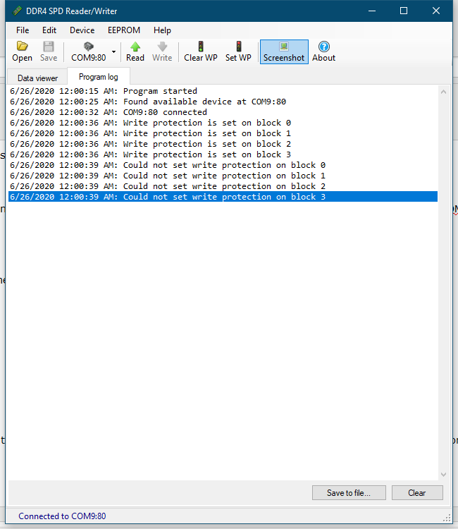


PropretorNo, I ran the program without Arduino. Apparently, this explains everything.


Without Arduino it shouldn't take that long to start the program.
 
Run the console program with /find switch and see if you have any other serial devices detected. If it also takes 10 seconds or more and still shows "Nothing found", then you might have one or more serial devices present which are being probed by programs.
 
Also check your device manager and see if you have anything under "ports" category.
2020/06/26 00:32:07
Propretor
a213m
 
No. According to schematic, closed jumper is for 5V/16mhz boards, open is for 3.3V/8mhz boards.

If the jumper is open on your board, then you'll have a 3.3V output on the VCC pin.

Many thanks!


2020/06/26 00:41:56
a213m
I updated the program, test timeout is reduced, the program should start 10x faster now when incompatible or conflicting devices are present + minor UI improvements.
 
https://github.com/1a2m3/SPD-Reader-Writer/releases
 
2020/06/26 01:13:40
Propretor

Very nice!
2020/06/26 01:33:05
Propretor
I apologize for the poor knowledge of Arduino. In addition, my Arduino boards are still being delivered and not received by me. But for compatibility with the GUI version of your program, do I need to use 7 or 12 pin?
2020/06/26 01:46:20
a213m
Propretor
I apologize for the poor knowledge of Arduino. In addition, my Arduino boards are still being delivered and not received by me. But for compatibility with the GUI version of your program, do I need to use 7 or 12 pin?


Do you mean a high voltage switch pin (HVSW value)?


Pro micro doesn't have pin 12. Any of 4 to 21 should work.
 
If you want to use Nano board, like the one I have, then either 7, or 12 will work.
 
Either GUI or console programs do not care what pins are used. When commands are issued from programs, Arduino handles them internally.
2020/06/26 02:07:44
Propretor
I focused on this scheme:

You want to say that without altering the code, I can use any of the contacts 4-9, 10, 16, 14, 15, A0-A3 ???
2020/06/26 02:25:42
a213m
Propretor
You want to say that without altering the code, I can use any of the contacts 4-9, 10, 16, 14, 15, A0-A3 ???


You'll only need to edit the value of HVSW constant to match digital pin number. Any of pins you listed should work. If the pin can work in analog or digital mode, like A5/D23, then you'll have to specify its digital value (23).


I like to use pin 13 because it is wired to the built-in LED, so that wherever write protection related commands are executed, the LED flashes, providing visual indication.

Use My Existing Forum Account

Use My Social Media Account