After seeing what happen to Lonelystoner's mobo, I though I might write a guide on how to repair tracks on PCBs.
When repairing tracks on something like a gfx, hdd or a mobo, it isn't as simple as just soldering a jumper wire to bypass the break. Why?
Well it comes down to physics and the way electrons behave at high frequencies. When a computer or any high speed circuit is designed all track positions, spacing, thickness and length are factored in to suit the particular signal. The physical layout affects: resistance, capacitance, inductance and propagation speed of the electrons them selves. Change these properties and the signals: distort/delay/advance/ lost/cross talk etc...
Therefore it is crucial that when repairing tracks that we maintain it to spec as close as possible. Ok here is my technique.
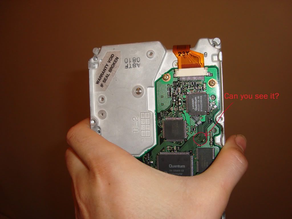
Today I used this old 3GB quantum hdd and punch a track with a knife for this demo.
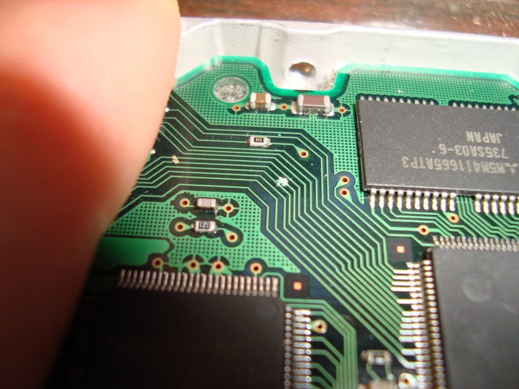
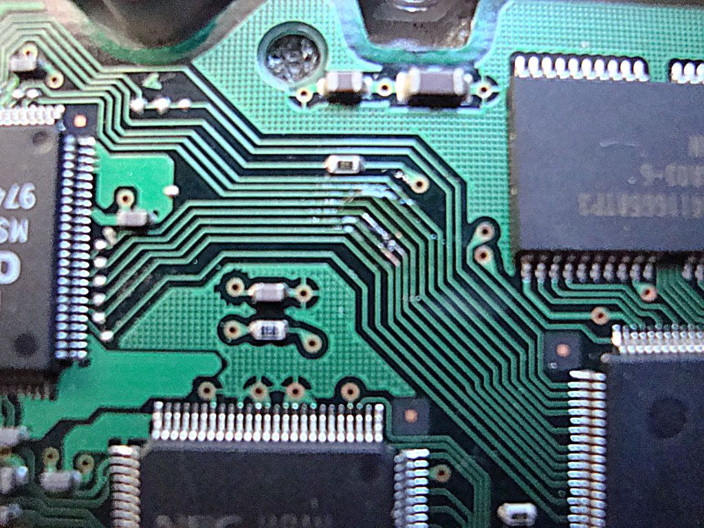
Ok thats is cut through. I start by using a jeweler's flat head screw driver and gently scrape the lacquer off a few mills down either side of the break until I see bare copper.
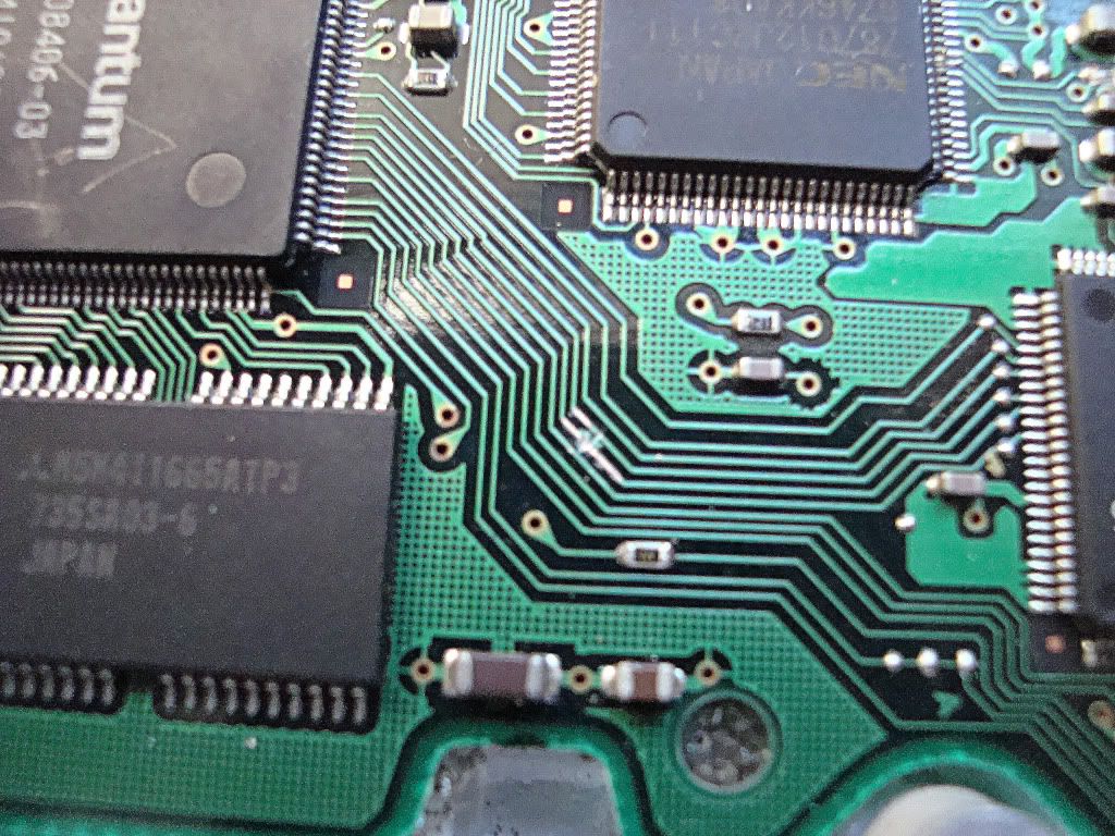
Next I get a good soldering iron, you can get Anti static ones or you can ground a normal one with a wire/aligator clip lead from the iron body to say? you computer case. This will ensure you dont kill what you are soldering. Also ASD mat or the bag the board came in to lay your work on.
Ok in the pic below you melt a blob of solder across the bare copper to tin it like so. then just lift it off after few sec. The blob will stay with the iron tip and leave it all tinned.
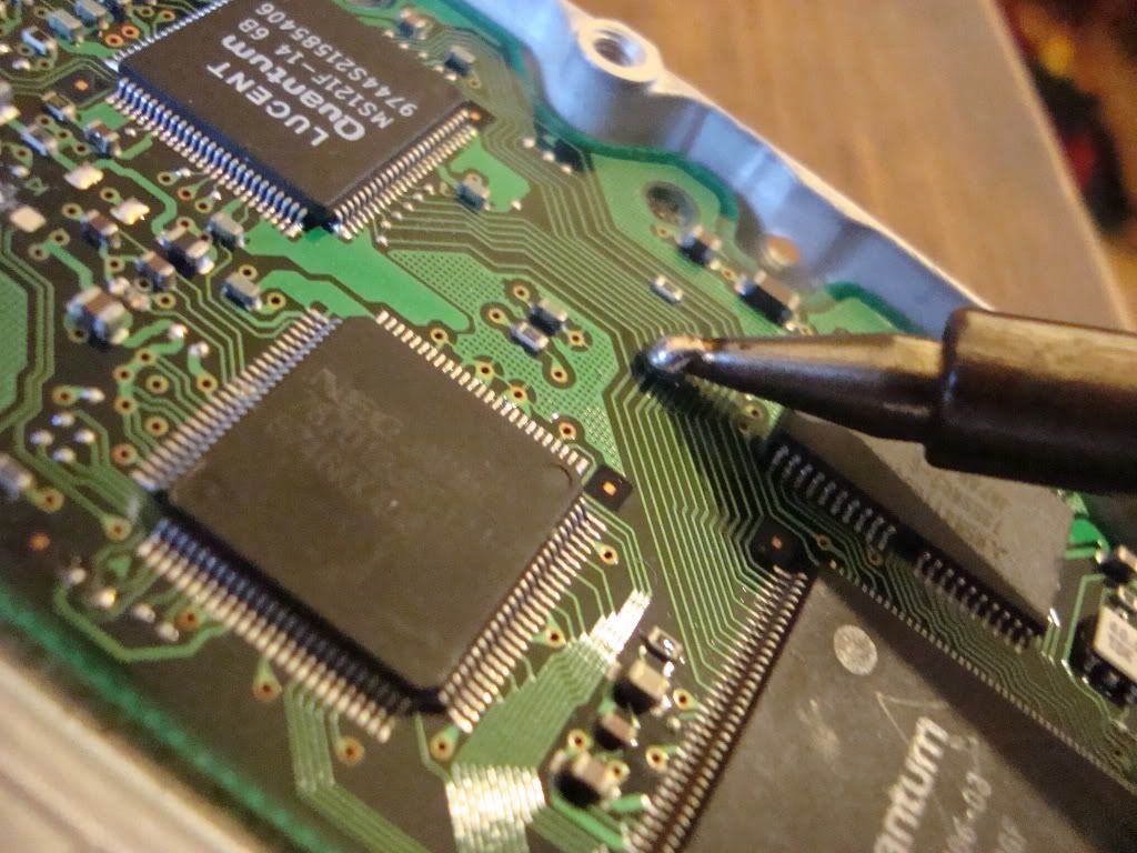
Now its all tinned. mmm looks nice

Now I get a wire and strip it until all the strands are out like this, then I tin one single strand. This will make it easy to solder it to the tracks.
Note! that was one rough looking tinning on that wire, it was for the purpose of the pic as I was holding the cam in one hand so I did it again after.
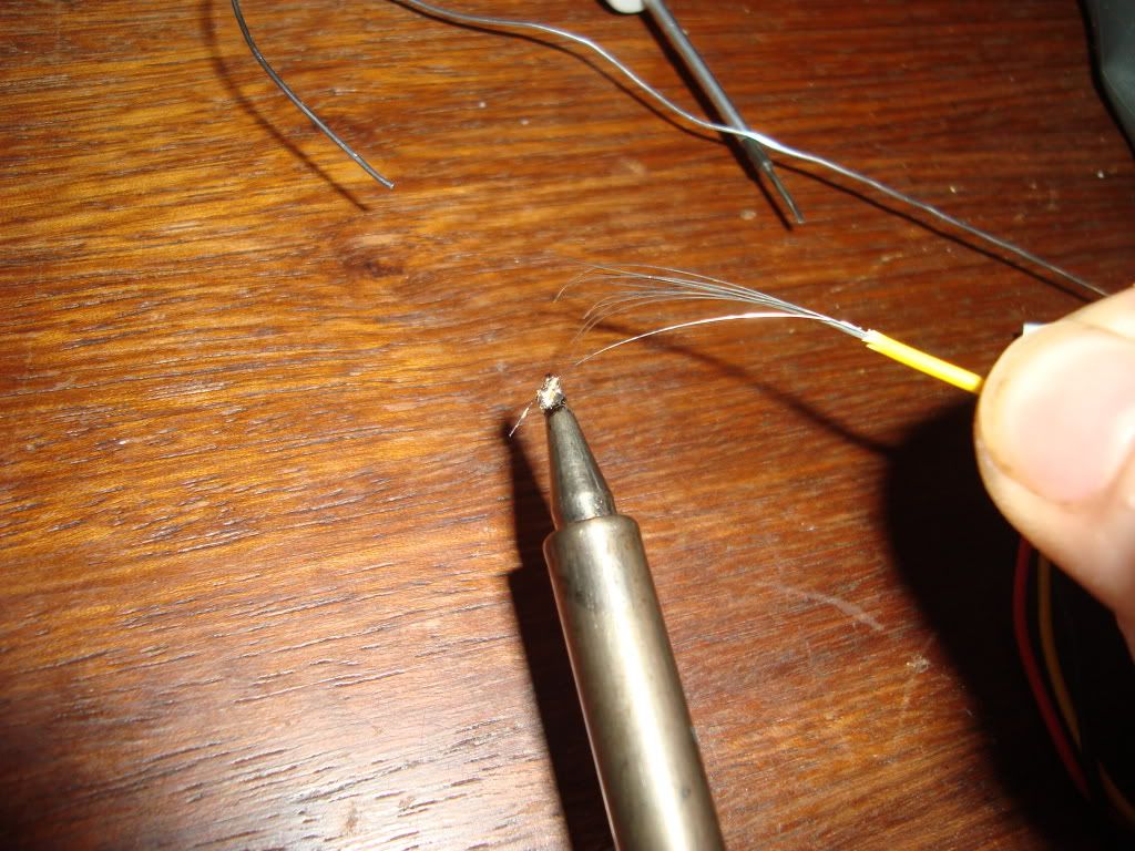
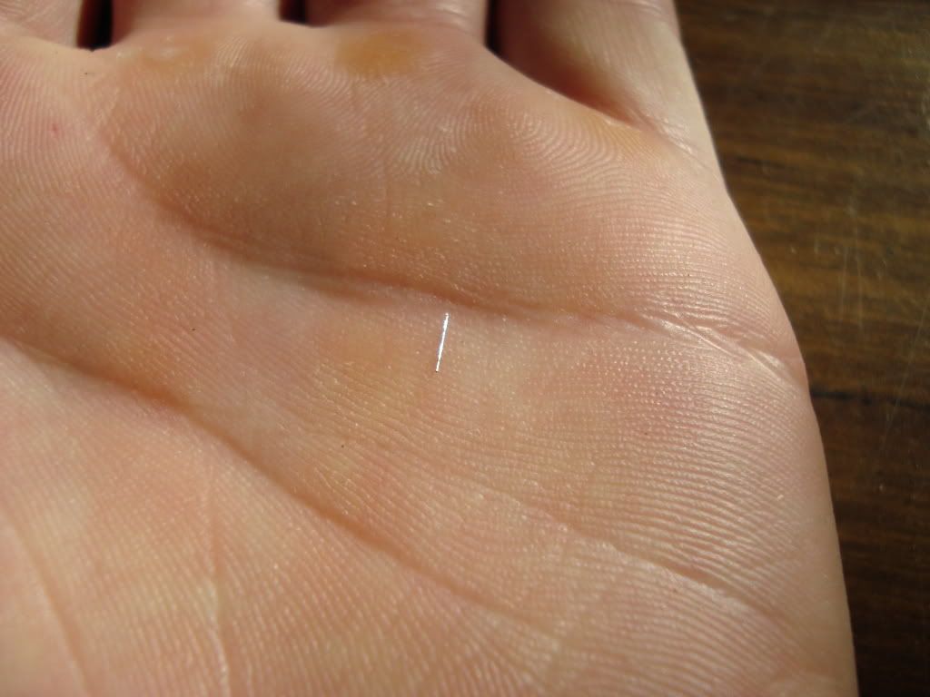
Then I cut the length needed, that was too much for this job in the pic. I ended halving it. If the track you are fixing goes around a bend shape this tinny wire to match.
Now I placed the wire on top of the break and heated one end then the other. Now it is soldered on. But wait! this is the hard part. To make sure you solder it on proper and good, I run a clean blob of solder across the whole lot, this also makes it very clean, neat and a strong connection. Here is the finished job

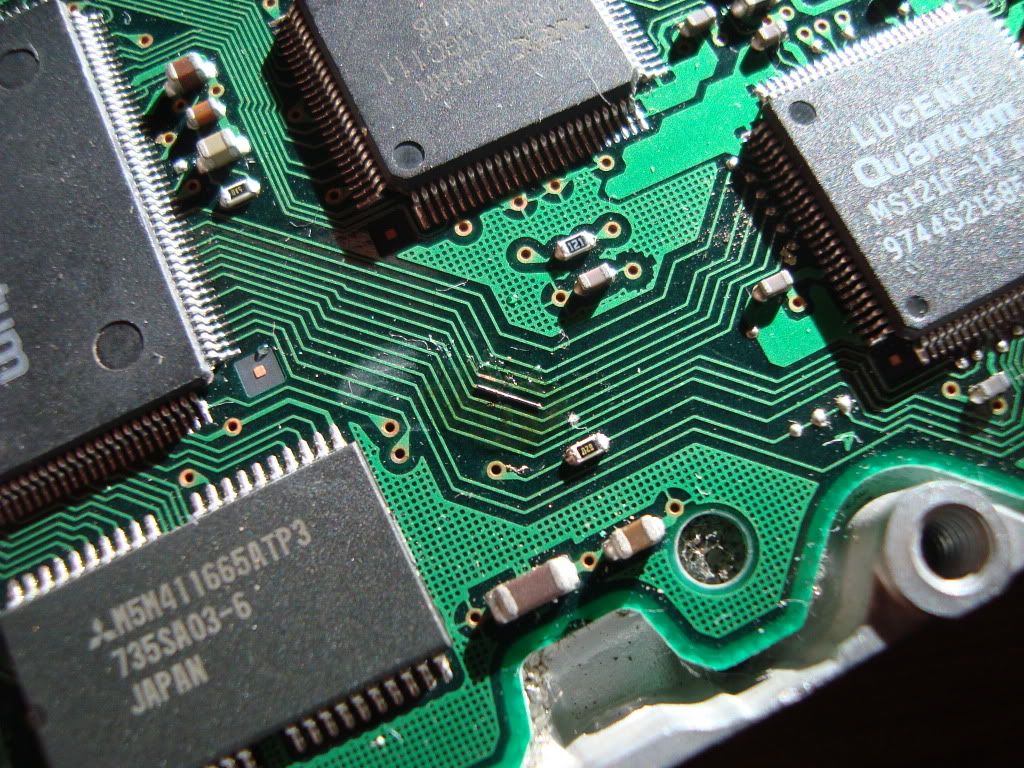
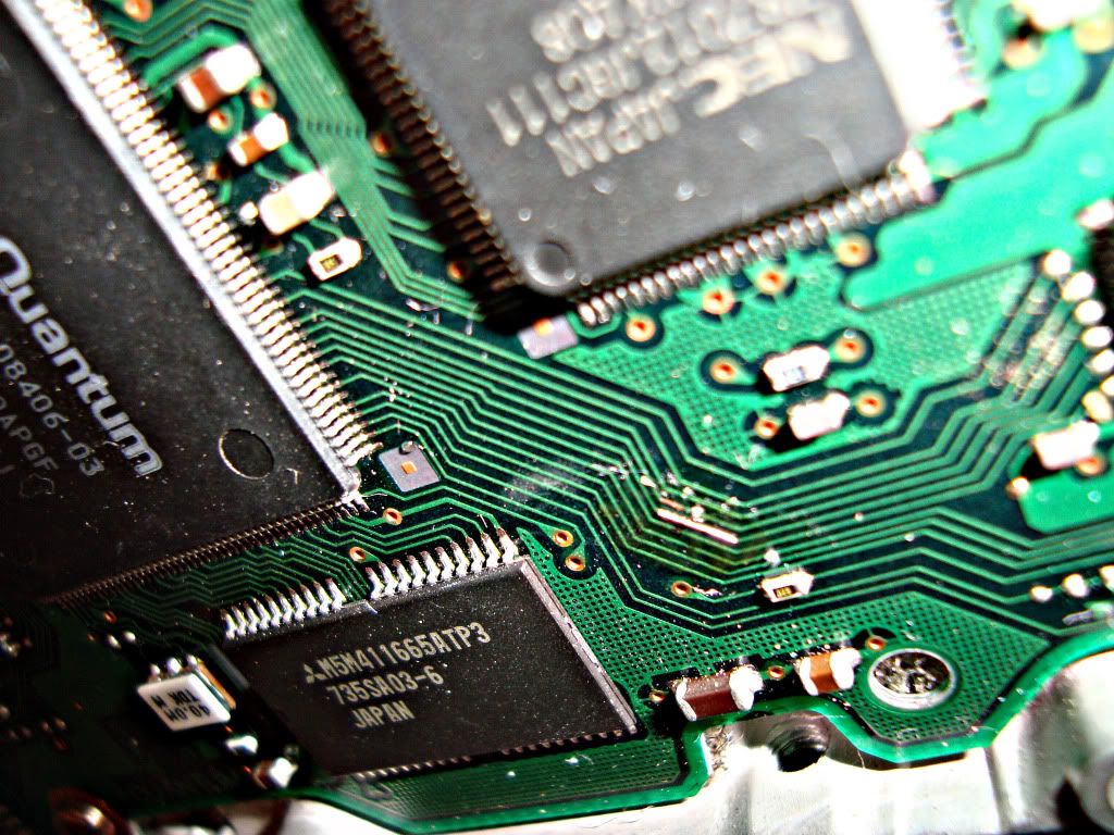
Use a multi meter to test connectivity by testing at the end points of the track, ie. at IC pins or PCI slot or what ever they lead to.
You can finish off the whole lot by insulating with some kind of adhesive, I like to use silicon sealant. This will protect against shorts against other objects ( back plates,screws, case blah blah) and also prevent the bridge from being knocked of if you accidentally knock it on something.
There! I hope that helps some one for future reference. I recommend doing this only if you can solder well if not get someone who can to help.