EVGATech_ChristianJ
Hello GammaLazer,
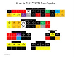
Using the diagram for the power supply pinout and the pinout for the motherboard side of the 24pin cable (linked below), you should be able to repair your cable. After the cable is repaired, I would recommend using the paperclip test and a multi meter to confirm all the pins have the correct voltage.
Hi, thanks so much for replying.
So the update is that I have made the New Cable using the pinout diagram for EVGA 18 + 10 layout on PSU side and 24 pin layout on motherboard side using your provided image.
Also with the help of paperclip test and multimeter I have verified every voltage and pin.
But have few doubts if you could clear.
1. Do all motherboards bear same layout as you have provided ? Mine is asus crosshair vi hero.
2. I have made mine using this diagram and everything tests perfectly. Should I plugin the motherboard?
3. Some of ports in Cable had capacitors in them, do I need to put them in original places? Mostly sleeved cables dosen't seem to have them.
Lastly the EVGA diagram attached above also has 24 pin layout which seems reversed to one you provided or am I reading it incorrectly?
Thanks.
Attached Image(s)