EVGA_Lee
Moderator

- Total Posts : 4247
- Reward points : 0
- Joined: 2016/11/04 14:43:35
- Location: Brea, CA
- Status: offline
- Ribbons : 14

Re: X299 Manuals posted
2017/11/29 10:41:32
(permalink)
GGTV-jon
After looking over (read as: scoured) the Dark manual I bummed about how things were configured for the larger m.2 slot and the primary u.2 port (page 28) for the 44 lane procs.
I take it it came down to trace layouts on the board? As this is different configuration then the FTWK.
My planned build has 1 m.2 as the primary OS drive and 2 u.2 drives for everything else. This leaves me wondering how the air flow over the 80mm m.2 will be without a restriction in the 110mm path way of the ducting.
Not that it is going to change my buying decision but I am curious as to what the rest of the on board sound components are to complement the Core3D CA0132.
Oh and HI - my first post here 
Yes, much different configuration than the FTW K. Unless your M.2 SSD is 110mm, you'd want to run your M.2 SSD in the PM2 80mm M.2 slot and enable both U.2 ports. The M.2 and U.2 ports will pull lanes from the CPU. If you're worried about the cooling, the I/O shroud is designed to have the air flow through both M.2 areas, and then exhaust out of the I/O panel in the back.
|
GGTV-Jon
FTW Member

- Total Posts : 1813
- Reward points : 0
- Joined: 2017/11/25 14:11:43
- Location: WA, USA
- Status: offline
- Ribbons : 19
Re: X299 Manuals posted
2017/11/29 21:20:42
(permalink)
EVGATech_LeeM
GGTV-jon
After looking over (read as: scoured) the Dark manual I bummed about how things were configured for the larger m.2 slot and the primary u.2 port (page 28) for the 44 lane procs.
I take it it came down to trace layouts on the board? As this is different configuration then the FTWK.
My planned build has 1 m.2 as the primary OS drive and 2 u.2 drives for everything else. This leaves me wondering how the air flow over the 80mm m.2 will be without a restriction in the 110mm path way of the ducting.
Not that it is going to change my buying decision but I am curious as to what the rest of the on board sound components are to complement the Core3D CA0132.
Oh and HI - my first post here
Yes, much different configuration than the FTW K.
Unless your M.2 SSD is 110mm, you'd want to run your M.2 SSD in the PM2 80mm M.2 slot and enable both U.2 ports. The M.2 and U.2 ports will pull lanes from the CPU.
If you're worried about the cooling, the I/O shroud is designed to have the air flow through both M.2 areas, and then exhaust out of the I/O panel in the back.
Thank you for the response Lee My concern was the air flow following the least path of resistance. With the flow path of the 110mm slot shorter and without the added restriction of an m.2 chip would adding some kind of non flammable stand-in help balance the air flow. Or does the m.2 header create enough restriction and the m.2 chip itself has little to no affect?

|
EVGA_Lee
Moderator
- Total Posts : 4247
- Reward points : 0
- Joined: 2016/11/04 14:43:35
- Location: Brea, CA
- Status: offline
- Ribbons : 14
Re: X299 Manuals posted
2017/11/30 09:40:52
(permalink)
Without any numbers to back this up, I would agree that cooling would probably be better in the 110mm slot, but overall, it shouldn't make much difference. You should place the included thermal pad for your SSD between the SSD and the board, and the airflow will also pull some heat away from that. The more important factor here is that you'll have constant airflow to the SSD regardless of which slot you'll use.
|
GGTV-Jon
FTW Member
- Total Posts : 1813
- Reward points : 0
- Joined: 2017/11/25 14:11:43
- Location: WA, USA
- Status: offline
- Ribbons : 19
Re: X299 Manuals posted
2017/11/30 21:38:58
(permalink)
Lee I would like to ask something just for planning clarification - I was looking at the Z370 forum section and was reading a post about a Z370 FTW (https ://forums.evga.com/So-many-issues-with-the-FTW-edition-m2732927.aspx). I know this is farther apart then the X299 FTW and Dark but the OP there had an issue with installing the OS on the lower M.2 slot on that board. Are we going to see this as well with the 80mm slot on the X299 Dark or will it be available for OS installation?
Reason why I ask is that I was originally planning on doing the OS install on a SAMSUNG 960 PRO M.2 512GB NVMe and use an 800gb u.2 drive for game installs and an 1.2tb u.2 for everything else. If the OS cannot be installed on a chip in the 80mm slot then I will have to rethink / plan my drive latout
|
bcavnaugh
The Crunchinator

- Total Posts : 38977
- Reward points : 0
- Joined: 2012/09/18 17:31:18
- Location: USA Affiliate E5L3CTGE12 Associate 9E88QK5L7811G3H
- Status: offline
- Ribbons : 282

Re: X299 Manuals posted
2018/01/12 18:12:41
(permalink)
I am Looking for a Guide for the LED's at the Upper Right Side of the X299 Dark Motherboard.
Their are 8 LED Lights and I am Showing Just Right of the Red CMOS Reset Button and Below the Diag LED;
1 2 3 4 5 6 7 8
O W O W W R W W
O = Off
W = White
R = Red
Thank you.
|
GGTV-Jon
FTW Member
- Total Posts : 1813
- Reward points : 0
- Joined: 2017/11/25 14:11:43
- Location: WA, USA
- Status: offline
- Ribbons : 19
Re: X299 Manuals posted
2018/01/12 19:55:10
(permalink)
bcavnaugh
I am Looking for a Guide for the LED's at the Upper Right Side of the X299 Dark Motherboard.
Their are 8 LED Lights and I am Showing Just Right of the Red CMOS Reset Button and Below the Diag LED;
1 2 3 4 5 6 7 8
O W O W W R W W
O = Off
W = White
R = Red
Thank you.
Pages 10, 11 and 13 of the manual get you close 
17. CATERR
a. CATERR stands for Catastrophic Error on the processor.
b. RED: Processor error has occurred.
c. OFF: No error state detected in the CPU.
18. FIVR
a. RED: CPU Fully-Integrated Voltage Regulator shutdown.
b. OFF: CPU is operating in a normal state.
19. CPU ERROR LEDs
a. CPU ERROR LED1
i. RED: CPU Logic detected error; system halted.
b. CPU ERROR LED2
i. RED: CPU Logic detected error; system halted.
c. CPU ERROR LED3
i. RED: CPU Logic detected error; system halted.
20. +5V Standby Power
a. RED: Voltage present (Does not mean PSU is outputting in-spec, only that this specific voltage is detected)
21. Memory Power
a. WHITE: Voltage present (Does not mean PSU is outputting in-spec, only that this specific voltage is detected)
22. +5V Standby Power
a. WHITE: Voltage present (Does not mean PSU is outputting in-spec, only that this specific voltage is detected)
23. Multifunction POST Indicator
a. During boot it will cycle many different hexadecimal post codes with a range of 00-FF and this indicates what aspect of the Power On Self Test (POST) is currently running.
i. For a list of POST Codes, please see Page 144.
b. This indicator can be configured in BIOS to display hardware monitoring information, such as voltage or temperature. After boot, these LEDs will show either temperature or voltage, depending on user configuration in the BIOS.
Attached Image(s)
|
bcavnaugh
The Crunchinator
- Total Posts : 38977
- Reward points : 0
- Joined: 2012/09/18 17:31:18
- Location: USA Affiliate E5L3CTGE12 Associate 9E88QK5L7811G3H
- Status: offline
- Ribbons : 282
Re: X299 Manuals posted
2018/01/12 19:57:12
(permalink)
Thanks, but still not seeing what the Red One Really Means.That is what I am reading is that my New CPU is Bad or my RMA'd Motherboard is Bad.What if any action can I or should I do? 19. CPU ERROR LEDsa. CPU ERROR LED1i. RED: CPU Logic detected error; system halted.b. CPU ERROR LED2i. RED: CPU Logic detected error; system halted.c. CPU ERROR LED3i. RED: CPU Logic detected error; system halted. It is #19 on that Image and Page."Are you on the EVGA discord?" No to this Tool. It is hard to read, at least for me. It Is #20 20. +5V Standby Power a. RED: Voltage present (Does not mean PSU is outputting in-spec, only that this specific voltage is detected) 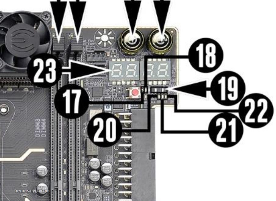
post edited by bcavnaugh - 2018/01/13 10:21:28
Attached Image(s)
|
GGTV-Jon
FTW Member
- Total Posts : 1813
- Reward points : 0
- Joined: 2017/11/25 14:11:43
- Location: WA, USA
- Status: offline
- Ribbons : 19
Re: X299 Manuals posted
2018/01/12 20:00:55
(permalink)
Would your #6 Red be the #21 in the picture? Are you on the EVGA discord? If it is #20 in the image then it is supposed to be red. I do not have a board here and am just trying to blow the pictures up. The one used above covers some of the LEDs with their art work / numbers Edit: Confirmed it is number 21 - had to really blow up one of the images in the manual with a clear shot of the LED layout and really blow up the image I posted above to confirm it is #21 "21. Memory Powera. WHITE: Voltage present (Does not mean PSU is outputting in-spec, only that this specific voltage is detected)" Can you connect your ProbeIt connector and check the voltage for the DIMM?31. ProbeIt Header The ProbeIt header is a means of live monitoring several different system voltages in real-time with a multimeter. One terminal needs to connect to a ground wire and the other to the specific you are trying to monitor. From top to bottom this is the function for each connector: VCore, Ground, DIMM, Ground, VCCPLL, Ground, VSA, Ground, VCCPLL_OC, and Ground.Image is page 14, quote above is page 24 Edit: See post below
post edited by GGTV-Jon - 2018/01/12 20:38:58
|
GGTV-Jon
FTW Member
- Total Posts : 1813
- Reward points : 0
- Joined: 2017/11/25 14:11:43
- Location: WA, USA
- Status: offline
- Ribbons : 19
Re: X299 Manuals posted
2018/01/12 20:30:11
(permalink)
bcavnaugh are you saying it is number 19 (the upper row of LEDs) and not number 21 in the lower row of LEDs? Did not see everything in your edited post above my post above - OK, number 19 Boy would have to figure out a way to ping TiN_EE or perhaps make a dedicated thread for this so they can take notice?
post edited by GGTV-Jon - 2018/01/12 20:37:41
|
bcavnaugh
The Crunchinator
- Total Posts : 38977
- Reward points : 0
- Joined: 2012/09/18 17:31:18
- Location: USA Affiliate E5L3CTGE12 Associate 9E88QK5L7811G3H
- Status: offline
- Ribbons : 282
Re: X299 Manuals posted
2018/01/12 21:49:13
(permalink)
GGTV-Jon
bcavnaugh are you saying it is number 19 (the upper row of LEDs) and not number 21 in the lower row of LEDs?
Did not see everything in your edited post above my post above - OK, number 19
Boy would have to figure out a way to ping TiN_EE or perhaps make a dedicated thread for this so they can take notice?
OK, thanks so then also your X299 Dark is not showing this then. I just did not want to Post a lot of posts in this Thread, sorry.
|
naokiura
iCX Member

- Total Posts : 376
- Reward points : 0
- Joined: 2007/05/04 14:56:13
- Status: offline
- Ribbons : 1
Re: X299 Manuals posted
2018/01/13 00:39:07
(permalink)
bcavnaugh
GGTV-Jon
bcavnaugh are you saying it is number 19 (the upper row of LEDs) and not number 21 in the lower row of LEDs?
Did not see everything in your edited post above my post above - OK, number 19
Boy would have to figure out a way to ping TiN_EE or perhaps make a dedicated thread for this so they can take notice?
OK, thanks so then also your X299 Dark is not showing this then.
I just did not want to Post a lot of posts in this Thread, sorry.
Are you sure it's not this one that is Red? Picture borrowed from Gobstoppable's 3 Dimm Post.  I have the same Red LED as this picture ... I to thought it was part #19 too till I saw his picture and looked at it again. If it then it's #20 and is normal, +5 Standby Voltage. Why did they have to make it RED when all the others are white?????
x299 Dark, i9-7920x, Corsair 3600 C18 32Gb, Corsair 1200AX, RTX 2080Ti FTW3 Ultra Hydro Copper, 2 - Samsung Evo Plus 1TB m.2
|
bcavnaugh
The Crunchinator
- Total Posts : 38977
- Reward points : 0
- Joined: 2012/09/18 17:31:18
- Location: USA Affiliate E5L3CTGE12 Associate 9E88QK5L7811G3H
- Status: offline
- Ribbons : 282
Re: X299 Manuals posted
2018/01/13 07:54:14
(permalink)
This is Referenced to the X299 Dark 51-SX-E299-KR Motherboard Only. naokiura
Are you sure it's not this one that is Red?
Picture borrowed from Gobstoppable's 3 Dimm Post.
I have the same Red LED as this picture ... I to thought it was part #19 too till I saw his picture and looked at it again.
If it then it's #20 and is normal, +5 Standby Voltage. Why did they have to make it RED when all the others are white?????
You are correct, I had to use Sun Glasses to see them. The Black Lines in the Manual make it hard to read the their Photo for old eyes. What I was thing or seeing above was not the Pins of the two LED Displays above. The Angle you can see your MB is Great I can not see mine this way and even a photo show only a Bright Light. Thank you and also thank you GGTV-Jon Pulling out the Bench Table to see what it shows us. 
post edited by bcavnaugh - 2018/01/13 09:14:37
Attached Image(s)
|
GGTV-Jon
FTW Member
- Total Posts : 1813
- Reward points : 0
- Joined: 2017/11/25 14:11:43
- Location: WA, USA
- Status: offline
- Ribbons : 19
Re: X299 Manuals posted
2018/01/13 16:17:17
(permalink)
bcavnaugh is the system booting OK and you just had a concern about that red LED?
|
bcavnaugh
The Crunchinator
- Total Posts : 38977
- Reward points : 0
- Joined: 2012/09/18 17:31:18
- Location: USA Affiliate E5L3CTGE12 Associate 9E88QK5L7811G3H
- Status: offline
- Ribbons : 282
Re: X299 Manuals posted
2018/01/13 16:38:50
(permalink)
GGTV-Jon
bcavnaugh is the system booting OK and you just had a concern about that red LED?
All is Great, only though the Red LED was Bad. The Crunchinator (Completed) & 
|
dustingg
FTW Member
- Total Posts : 1647
- Reward points : 0
- Joined: 2012/04/19 10:44:46
- Location: Newport beach CA
- Status: offline
- Ribbons : 7
Re: X299 Manuals posted
2018/02/07 15:50:09
(permalink)
Can we expect a detailed BIOS manual for these boards?
ROG Z790-APEX : 13900KF (RTX4080)EVGA Z370-FTW: 9900KF (RTX3080)Associate Code: VOM7YYOWC5ADWTWYouTube RigPics Twitter

|
Bobmitch
Omnipotent Enthusiast

- Total Posts : 8328
- Reward points : 0
- Joined: 2007/05/07 09:36:29
- Status: offline
- Ribbons : 47
Re: X299 Manuals posted
2018/02/07 20:42:19
(permalink)
I hope so. Still trying to figure out what the difference between AUTO and Disable is in C States setting. I know exactly what Disable does (runs CPU at FULL overclock with no rest) but AUTO seems to do the same thing...
MSI MAG X670-E Tomahawk; Ryzen 7 7800X3D; Asus TUF RTX 4070 TI OC; Seasonic Vertex GX-1000 PSU; 32 GB Corsair Vengeance DDR5-6000 RGB; Corsair iCue Link H150i RGB 360MM AIO; 2-Western Digital Black 4 TB SN850X NVMe; Creative SoundBlaster Z; Lian Li Lancool III; EVGA Z15 Keyboard; Razer Viper 8K Mouse
Heatware: http://www.heatware.com/eval.php?id=72402 Affiliate code: 1L2RV0BNQ6 Associate Code: UD82LJP3Y1FIQPR
|
bdary
Omnipotent Enthusiast
- Total Posts : 10330
- Reward points : 0
- Joined: 2008/04/25 14:08:16
- Location: Florida
- Status: offline
- Ribbons : 116
Re: X299 Manuals posted
2018/02/08 09:55:08
(permalink)
bobmitch
I hope so. Still trying to figure out what the difference between AUTO and Disable is in C States setting. I know exactly what Disable does (runs CPU at FULL overclock with no rest) but AUTO seems to do the same thing...
If your CPU is overclocked, and you have C States set to Auto, check your power options > advanced power settings > Processor power management > minimum processor state in Windows. If you have that set to 100%, I don't think your CPU will idle down. You may want to try (if you want the CPU to idle) something like 30% or less as a minimum to see if that does it.
|
bcavnaugh
The Crunchinator
- Total Posts : 38977
- Reward points : 0
- Joined: 2012/09/18 17:31:18
- Location: USA Affiliate E5L3CTGE12 Associate 9E88QK5L7811G3H
- Status: offline
- Ribbons : 282
Re: X299 Manuals posted
2018/02/08 23:36:37
(permalink)
bobmitch
I hope so. Still trying to figure out what the difference between AUTO and Disable is in C States setting. I know exactly what Disable does (runs CPU at FULL overclock with no rest) but AUTO seems to do the same thing...
I am seeing the same on the X299 MB as well.
|
Desamis
New Member

- Total Posts : 100
- Reward points : 0
- Joined: 2018/03/14 10:57:41
- Status: offline
- Ribbons : 0
Re: X299 Manuals posted
2018/03/14 11:35:22
(permalink)
|
hotrod717
New Member
- Total Posts : 20
- Reward points : 0
- Joined: 2013/01/13 07:16:16
- Status: offline
- Ribbons : 0
Re: X299 Manuals posted
2019/04/11 15:49:42
(permalink)
|
Zeddivile
SSC Member

- Total Posts : 761
- Reward points : 0
- Joined: 2017/09/30 11:15:15
- Location: @ the tipity top of FPS mountain
- Status: offline
- Ribbons : 7
Re: X299 Manuals posted
2019/07/27 18:35:14
(permalink)
Thx to this thread I am no longer worried about that LED. Did have flashbacks to when I had a non lit LED on the z390 Dark also turned out to be a non issue
"This stuff breaks my tiny often dehydrated and carb deprived hamster brain" -2019  
|